![]()
German S-100 Class Schnellboot (Fast Boat)
The SBoot 1/35th scale Hull Kit
I will be separating the various scale hulls into their own pages as they are diverging due to material sizes and other factors - I am also working on a 1/30th scale
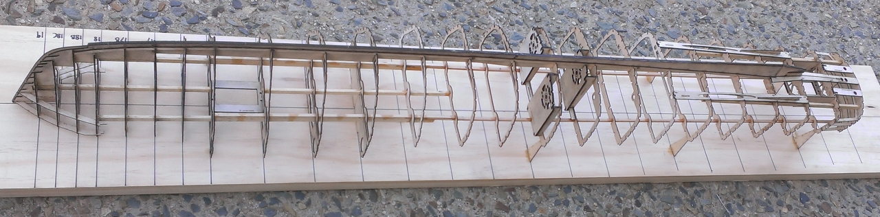
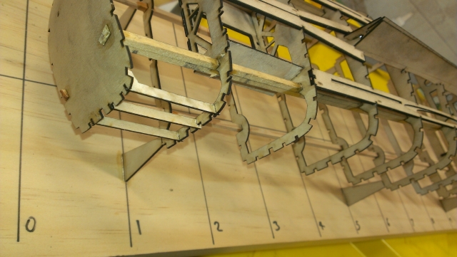
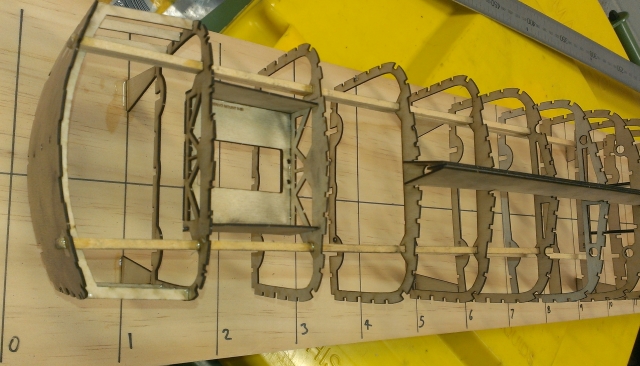
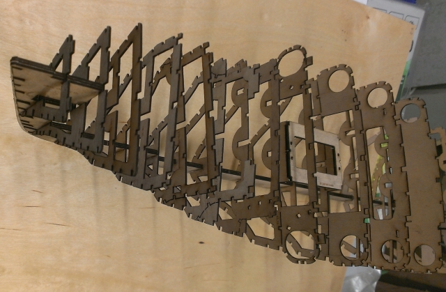
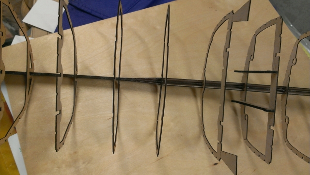
This is the finished 1/35th scale skeleton kit with only the deck runners fitted, there are no stringers, chine or gunwale timbers shown here yet. The original S100 was 35 Metres long so at 1/35th scale the model is 1 Metre or 39.4" long.
I left the photo's as numbered by my camera so the earliest photo is at the bottom of the page and progresses to here.
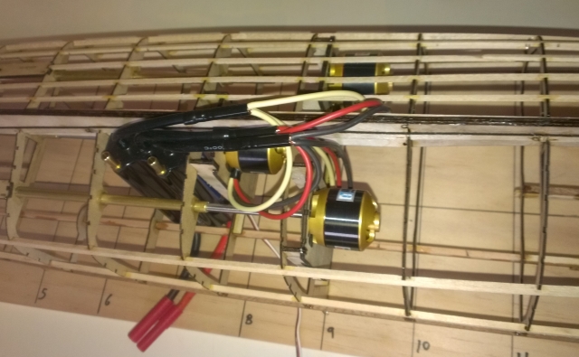
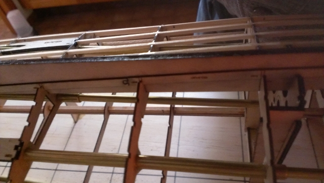
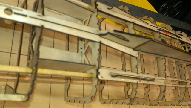
This is a side view of the motor mounts, for picture clarity I have only fitted the stringers to the opposite side.
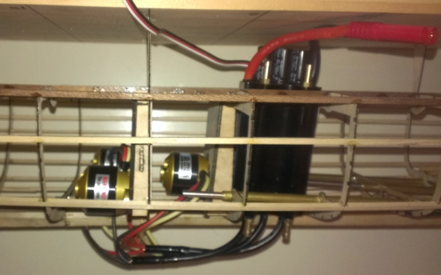
I wired all three motors to a single speed controller, which sort of works as long as they are all running free, a bit of weed around one propeller may cause issues though!
Three motors fitted.
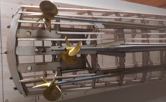
Three 35th scale S-Boot props. I don't have any cast struts or rudders for this scale.
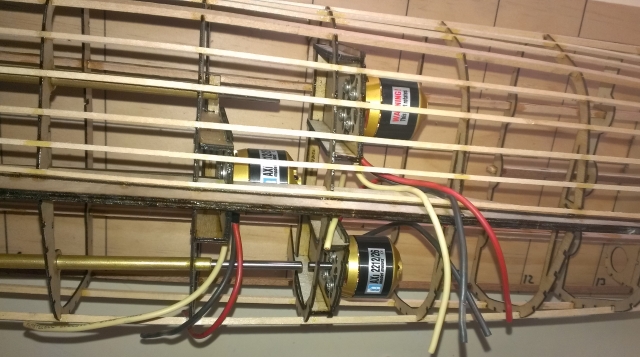
The motor mounts shown with the prop shafts pushed all the way through to check their alignment.
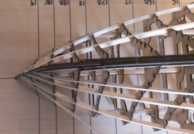
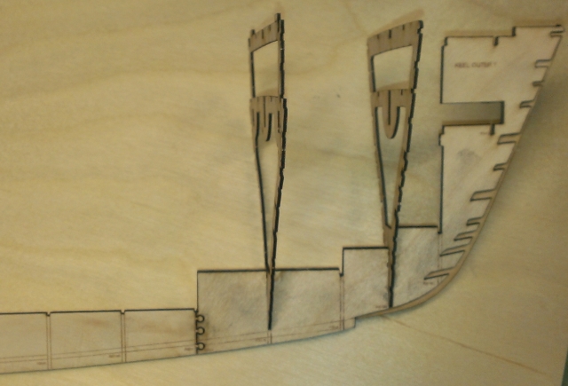
This shows the extra keel that runs beside the main keel and gives us something to finish the planking against.
The prop shafts fitted.
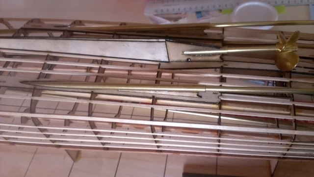
The prop end of the three shafts and this picture also shows where the main centre shaft emerges from the keel.
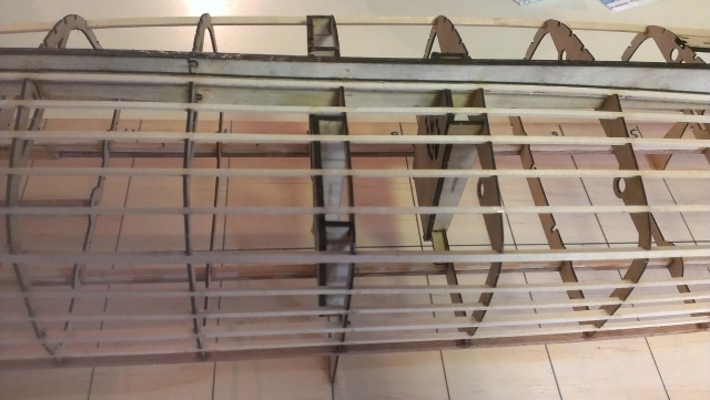
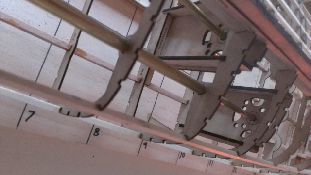
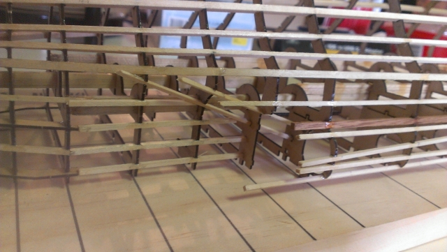
This shows all the stringers fitted to one side only, I did this for clarity in documentation but I wouldn't normally do this as it could end up bending the hull.
The aft end view of the stringers all finished on one side.
All the stringers all in place on one side.
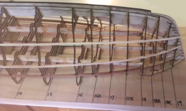
The gunwale and chine stringers in place on both side.
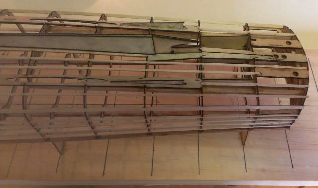
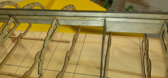
You need to make sure all the ribs stay in the right place as you add the long timbers, especially where the torpedo doors are.
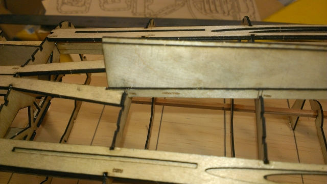
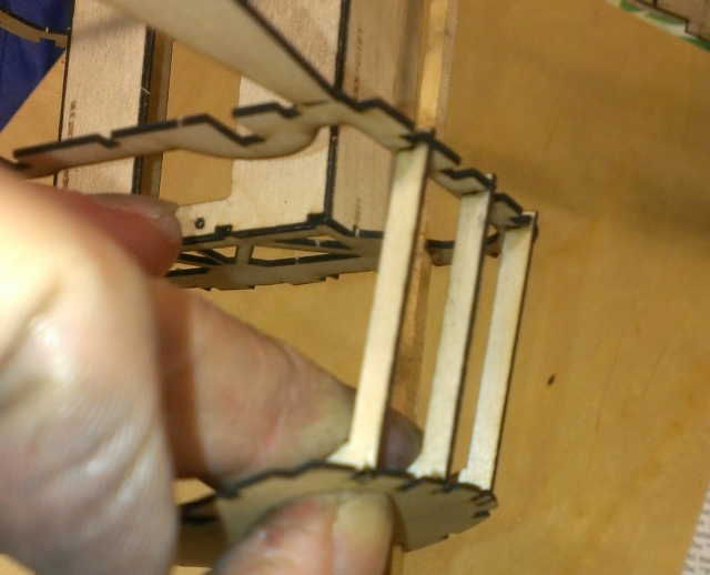
The torpedo cutout has a few short timbers sloping down towards the keel to support the deck cutout infill panel.
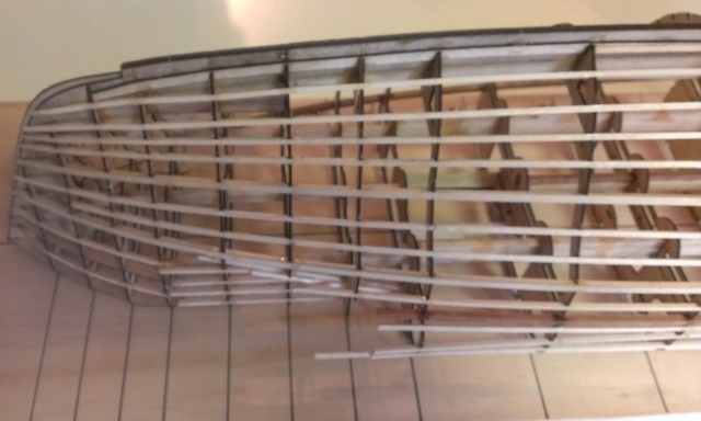
You can use some pegs or clamps to hold the timbers in place until the glue has fully hardened.
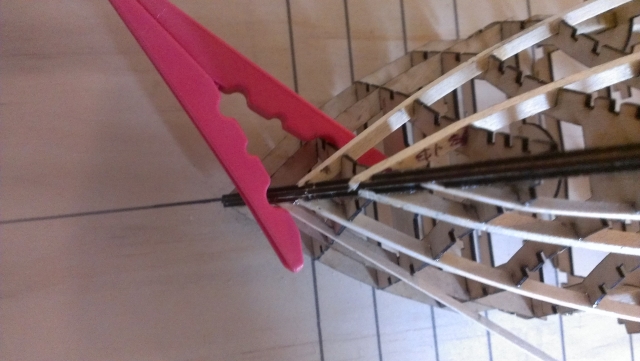
Make sure the ribs don't move when bending the timbers around the bow, it's easy for them to be pushed towards the stern.
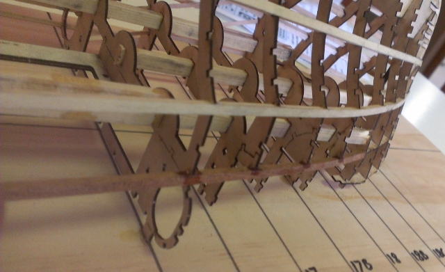
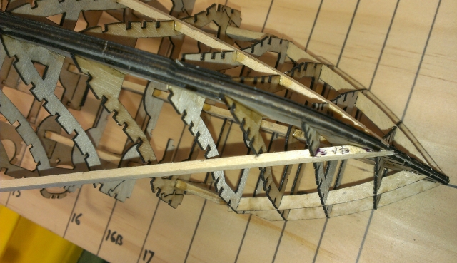
It's easiest to start the stringers from the bow, cut them at approximately 45 degrees where they meet the bow sprit.
The larger chine timbers can be hard to bend, you could steam them first. Try to get timbers with a similar feel or bending strength, it isn't hard to bend the whole structure at this point so check the straightness of the keel often!
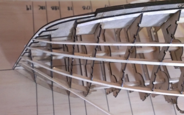
This shows the chine timber at the stern, the chine is wher the side of the hull becomes the bottom, the Schnellboot has a rounded or "soft" chine rather than a hard change of angle like the US boats.
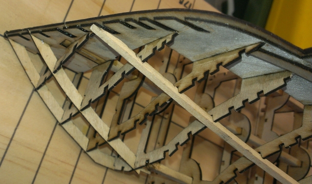
Start adding the larger long timbers and alternate from side to side, make sure they are all pushed fully home in their slots. This photo shows the chine timber which isn't really a chine at the bow but it runs the legth of the boat.
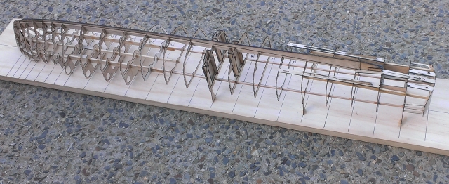
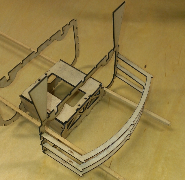
The hull kit finished, before adding all the stringers, chine and gunwale timbers.
There are three main runners at the bow and the outside two travel the length of the boat.
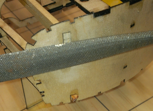
File or sand off the main runners where they emerge from the transom, there is another transom layer over all these ends once they are all smooth.
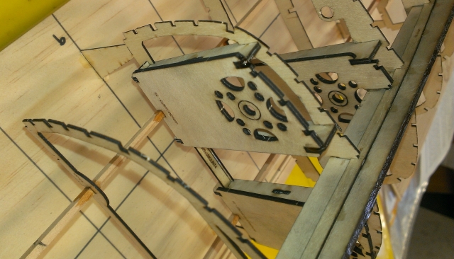
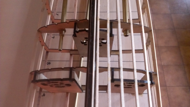
The wing motor mounts in place.
The wing motor mount wedges in place and a brace across the top, again these line up the motors at the same angle as the wing prop shafts.
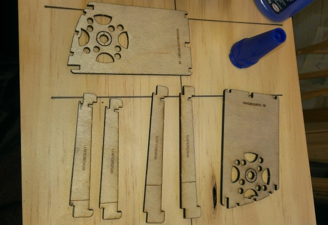
The various pieces of the wing motor mounts.
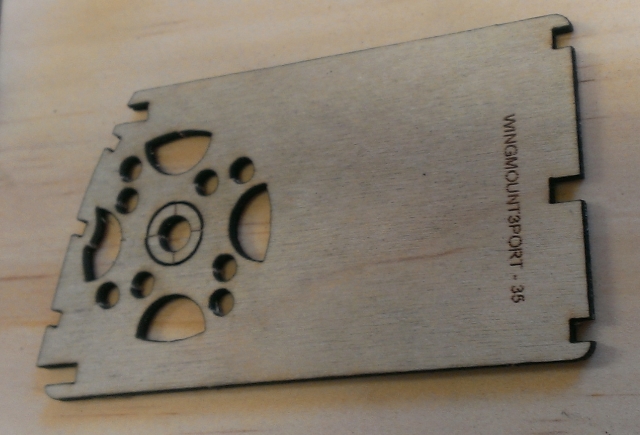
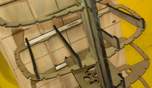
The port wing motor mount laminated together. These tie into the stringers and the covering so they are really solidly mounted.
The centre motor mount in place on the wedges, all these pieces are double thickness for strength.
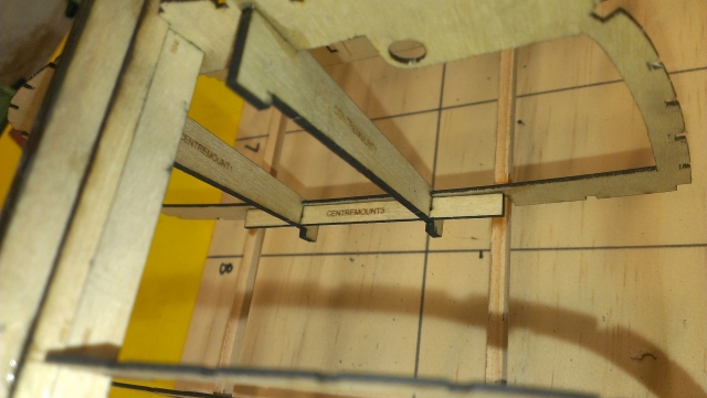
The motor wedges have a strengthener at the top of the rib to stop them twisting and hold them square.
Another view showing the infill wedge in place as well as the final pieces of the main keel where the main prop shaft will emerge.
There is a long slot in the outside layer of the wing keel for an infill wedge piece between it and the wing prop shaft.
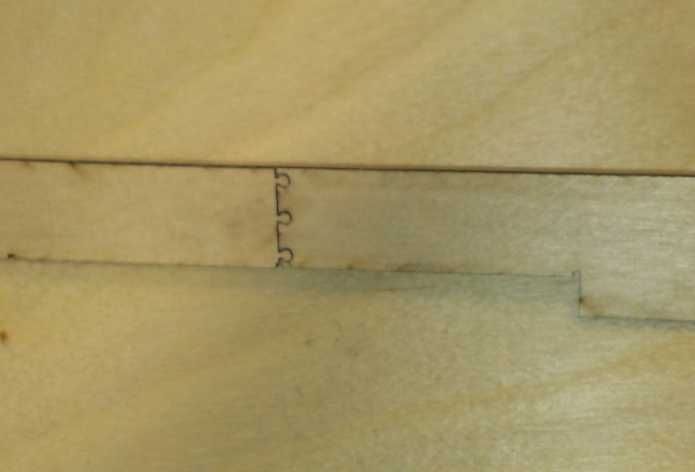
Another view showing the jigsaw join in the extra keel, again these are in different places to the joins in the main keel for added strength.
The extra keel pieces extend all the way to the centre prop shaft.
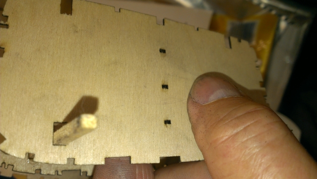
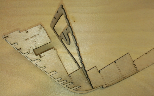
There are extra small keel pieces beside the main keel in line with the ribs, this is to attach the planking to. Also there is a step in the keel where the keel emerges and blends with the bow.
A rear view from the port side.
A view of the main motor mount wedges, these are there to line up the motor angle with the prop shaft angle.
This shows the starboard wing keel or shaft log fitted.
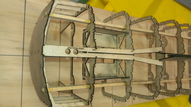
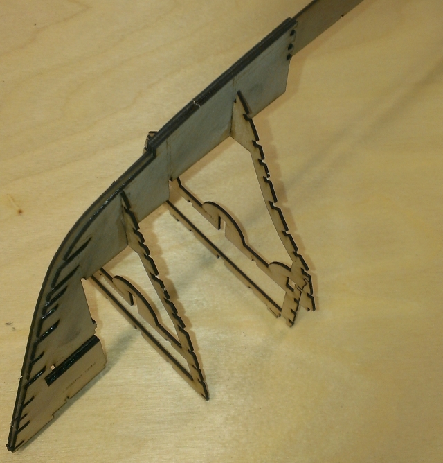
The centre rudder keel is split almost all the way along to allow it to twist to the rib shapes as it goes forward.
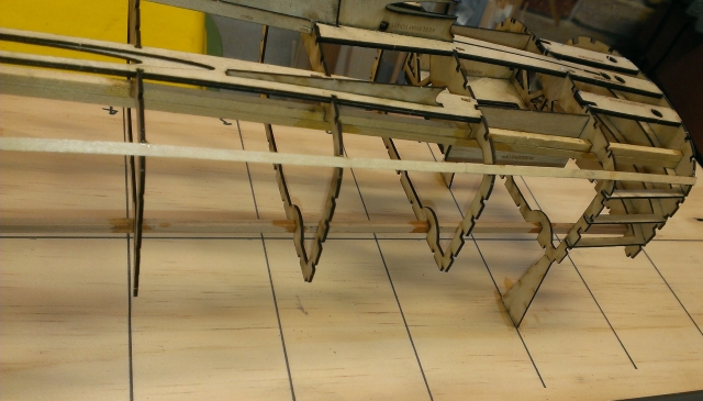
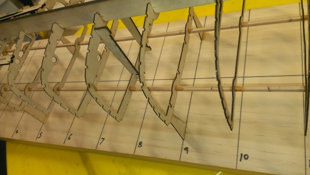
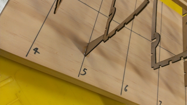
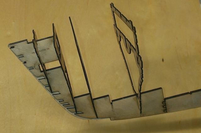
This shows all the ribs in place and all glued down and you can see how the main keel turns into an "A" frame where the main prop shaft fits.
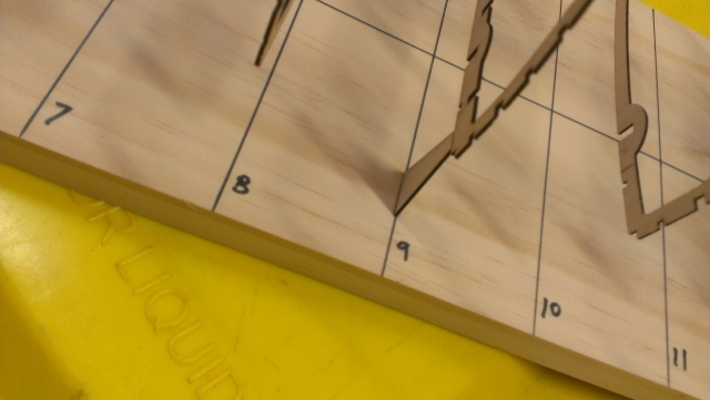
When you glue the ribs down make sure they are equal spacing either side of the base board centre line.
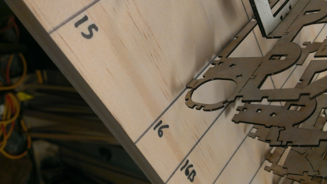
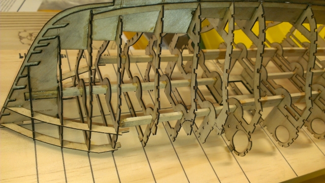
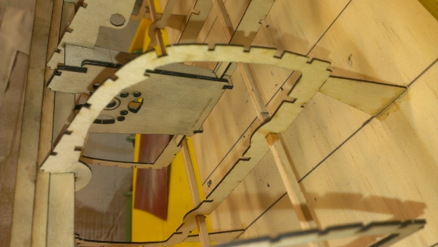
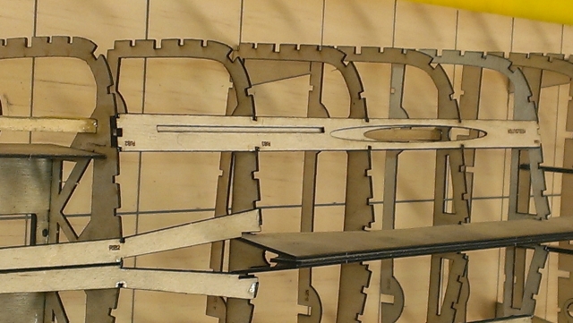
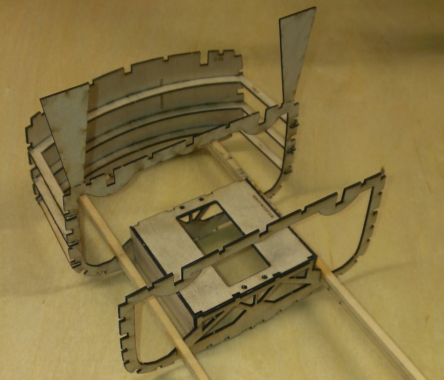
Here you can see that the torpedo tube holes can be broken away and a lower deck profile exposed at rib 16, also as you look further to the lower right of the photo you can see the torpedo deck cutout can be left in place if you want to.
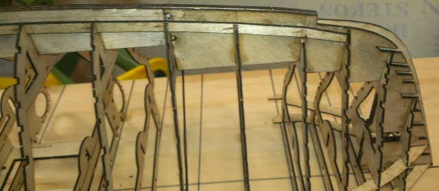
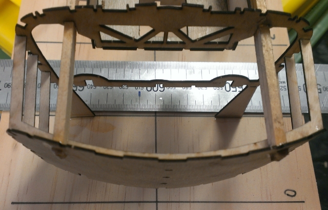
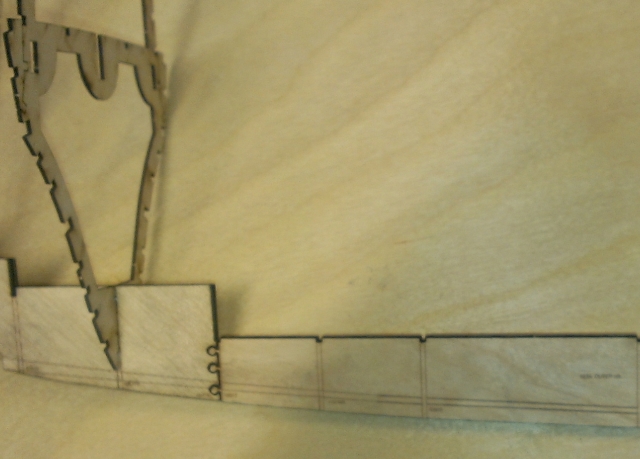
At the bow the mounting tags are very short, just allowing for the curved deck. The chine and gunwale timbers are replaced with laser cut pieces at the very front so that the curve ends up correct as it's easy to bend the bow out of shape otherwise.
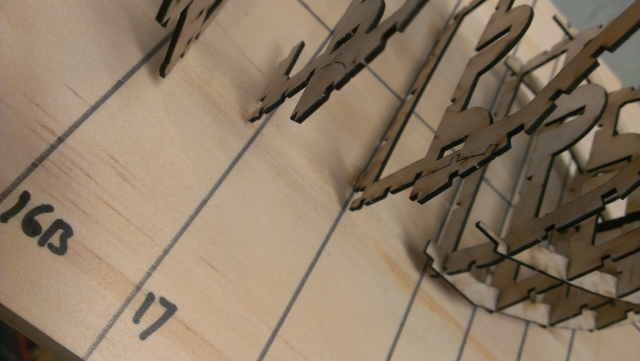
The mounting tags get longer towards the rear of the boat to cater for the high forecastle at the bow. You can build it without the high forecastle if you want to build an earlier version, which had the torpedo tubes mounted on the deck.
Only some of the ribs have tags to glue them down, these are designed to be broken off at the deck level later on.
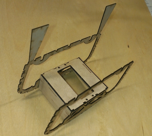
The bow section from the base board side, ordinarily I would have glued it down to the baseboard by now but as I was checking everything I wanted to be able to fix any issues. Here you can see some of the small tags which are used to glue it down.
There is a full size servo mount in the bow section to operate torpedo doors or to move the forward cannon, your choice.
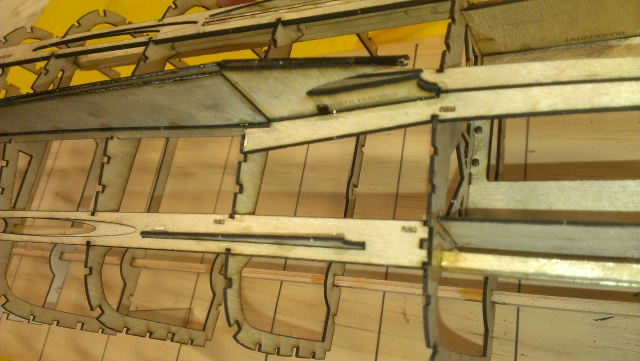
Here you can see where the main keel starts to become a "V" shape, this is to accomodate the centre prop shaft which goes through the keel. You can also see the mounting wedges in place for the centre motor mount.
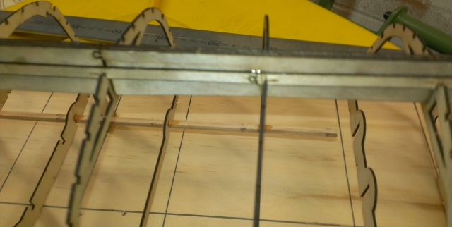
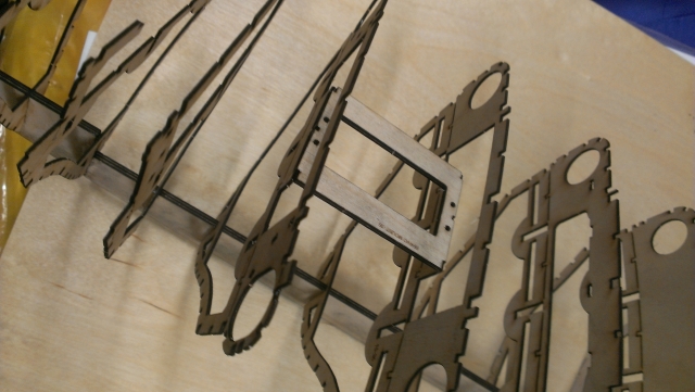
I put two extra strengtheners through the rear end of the boat so it can't "break it's back".
The wedges fit into notches in the transom, you may need to clamp these, even with cyanoacrylate glue. You could steam the transom to curve it first.
There is an inner transom with holes to line up the various runners and wedges.
The transom wedge sections are there to space the transom and form the curved shape of the stern (transom).
Make up the rear rudder servo mount section.
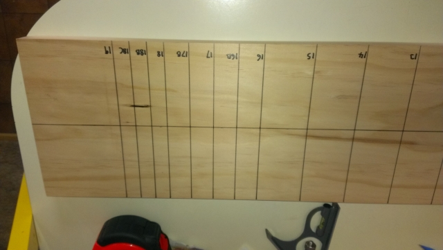
Mark up your base board and glue the bow section down when it gets a bit cumbersome and fragile.
The centre and outer keel sections are joined in different places for strength.
All the keel joints are jigsaw joints and they are all different so you can't easily put them in the wrong place.
Make sure the very front rib is inserted before the next one or it won't fit in later.
Add to the keel as you go, making sure it is perfectly straight.
Add each rib in turn and again make sure they are all pushed firmly "home".
Start by building up the bow section, first the three layers of the main keel, and then dry fit each rib, making sure each one is firmly interlocked with the keel and fully pushed "home".
(C) Copyright 2016 - 2018 - John Drain