The Hull 2 - 1/20th Skeleton Kit
note:If you would like a cheaper version, see the Hull-2 MDF Version
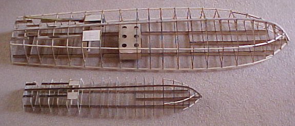
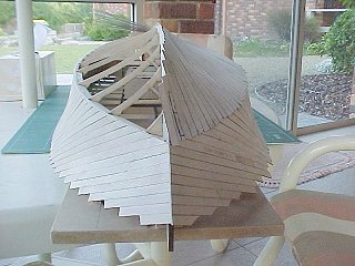
1/20th scale (4') top and 1/35th scale (27.5") models side by side.
Hull-2 Skeleton Kit is now available again in both 1/20th scale (4' long) and 1/35th scale (27" long) versions.
I have finished the design of the Hull-2 1/20th scale Hull skeleton kit and I have also finished the 9 pages of instructions with lots of photo's about how to build it, I have increased the number of parts to 122 see the pricelist for details.
Based on my years of research, many books, photographs and the few available original drawings that I have managed to get hold of I spent many thousands of hours re-creating and re-drawing the original boat plans (which is an ongoing project) and based on these plans I have developed the new, more accurate, 1/20th scale (4' or 1220mm long) and the 1/35th scale (27.4" or 697mm long) model hulls available as laser cut rib sets of approximately 122 pieces. Please don't ask me for AutoCAD files as refusal sometimes offends!
The laser cut 1/20th scale kit includes 20 ribs, transom, laminated main keel, laminated wing prop shafts and separate rudder keels, breakaway laminated deck runners which includes the deck opening upstand, motor mounts, servo mounts, a large battery box and a laminated stand. These parts are cut from very fine grade 2mm (5/64") thick GL3 Birch ply from UPM in Finland and are supplied on 8 separate sheets that are 300mm x 400mm (1' x 1'4"), this makes a 16mm (5/8") thick stack that can be shipped as a flat cardboard box by airmail and will weigh around 1.3Kg (3 pounds). This is an important consideration as I am in Australia!
The long keels when made up, are laminated as 4 thicknesses of 2mm ply with 6 thicknesses at the prop shafts and rudders, the deck runners are 2 thicknesses, the individual short pieces are fitted together end to end with staggered jigsaw like joints. All individual kit parts join together into slots or recesses and make for a very strong but lightweight hull frame that is fairly easy to build. The motor mounting board is designed to take every type of motor that I currently have or have previously used in Hull 1 and can be set up as either a geared or direct drive arrangement.
You will need to supply the long chine and gunwale timbers and the hull covering materials as well as the running gear. The chine and gunwale are 4mm (5/32") square section material as full lengths (1200mm plus or 4' plus) of balsa or harder wood such as Ramin or Spruce and you can cover the hull in whatever you like, I am using 2 layers of 0.8mm (1/32") Birch ply which I have laser cut into 1/20th scale 6" wide planks, just like the real thing which was covered in two layers of 1/2" Mahogany planks with waterproofed muslin cloth between the layers.
Model Hull 2 varies from Model Hull 1 in the following ways:
1. The motors are mounted close to the original location and are much further aft (rearward) than in Hull 1, this means that the prop shafts are much shorter and can be bought as complete 8" types rather than having to make them up yourself. I have allowed for both 6.35mm (1/4") or 8mm outside diameter prop shafts. Moving the motors means that the boat will be balanced better as the batteries will be further forward in front of the motors.
2.The Hull 2 shape has a much more concave profile in the sides and bottom which is as close to the original Elco PT103 class 80' hull drawings as I can get it.
3. The propeller shafts are parallel to each other like the original full size boat and not tapered outwards like Hull 1 which gives more room for larger motors up to Speed700 / 775 size.
4. The wing rudders are splayed outwards at the aft hull bottom angle like the original Elco boats, this should help the boat turn better by helping the bow to not "dig in" or have the stern trying to lift with the parallel rudders in a tight turn due to the angle of the hull in the water as it leans into the turn.
5. Hull 2 is very accurately laser cut so there is a heap less drudge work involved in building it, for those that have not built Hull 1 there is a LOT of work just cutting out ribs and making up the propshafts, gearbox etc and the end result should be a much more accurate lighter and "tighter" hull. The whole Hull-2 skeleton can be put together in a couple of days!
I am working on the superstructure kit(s) currently and revising the torpedo roll off rack kit which will also be available shortly.
I will do an extreme model soonish (but please don't hold your breath). This model will have all 69+1 ribs with Veedrive gearboxes and Packard engines but I may produce it as a half hull to show off the interior.
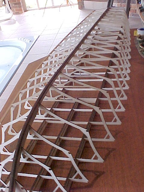
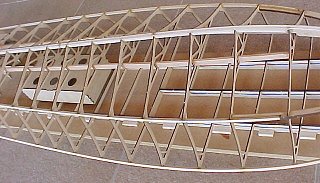
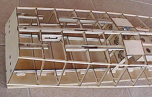
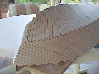
This is an example of the layout of the laser cut skeleton kit for the new 'Hull 2' at 1/20th scale.
(There is still quite a lot of waste material left so I am adding extra pieces that I can include that can also be cut from 2mm ply.)
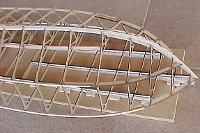
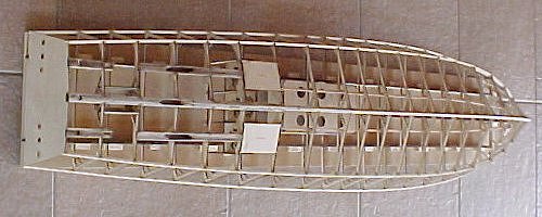
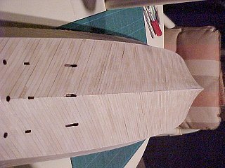
This is the 1/20th Skeleton kit finished, sanded and ready for planking.
Finishing the Skeleton Kit into a boat
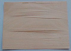
I looked at the available planking materials and the price and I decided to make up some 1/20th scale 6" planking (7.62mm wide) using the laser cutter, I was going to use scale 0.6mm birch ply but it's just a little bit too flimsy so I settled on 0.8mm which if scaled up to the full size boat would make the overall covering thickness (two layers) 32mm or about 1 1/4" thick, which if you consider the original boat had two layers of 1/2" planking and a layer of muslin cloth and glue in between it would have come out thicker than 1" anyway and with some sanding the covering will get somewhat thinner. I get 39 strips out of a 300 x 400mm sheet and each strip is a pretty good length to do two strips at 45 degrees or so on the hull surfaces, that's about 15 lineal metres or 50 lineal feet of planking per sheet. I used about 8 sheets to do the entire covering in two layers.
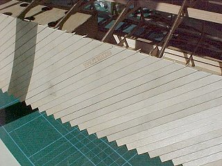
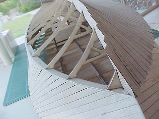
The First Layer
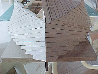
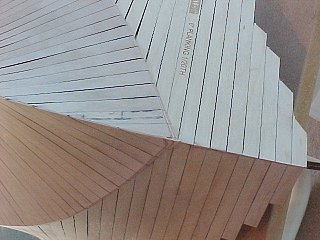
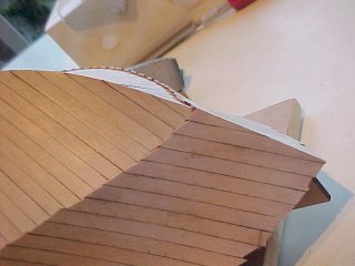
Plank one side starting near the bow, where it meets the chine, glue the planks to the ribs and chine timbers but NOT to each other on the first layer, this will leave some flexibility for the planks to move in between the ribs when the second layer is added later at the opposite angle. Generally it works best to plank "upwards" so that the glue runs down on the last plank so start near a bottom corner but you don't want to start right at the bow or all of the aft timbers will want to be bent to fit against the last one as the twist in the planks at the hollow bow makes the middle of the plank seem fatter. It doesn't really matter if you can see daylight between the planks on the first layer just allow the planks to find their own curve. I cut the excess planking off at the chine with a good pair of side cutters (nail clippers should work also). There should be about 110 strips per side depending on the angle, I ended up with 3 or 4 more on one side, not important on the inner layers.
I let the hull shape choose the angle where the wood wanted to go near the bow and then made sure that I could get two strips out of each length of planking without too much waste. If the angle is chosen correctly the strips will be fairly straight end to end with just a twist to take up the hull shape. Then file or sand off the chine to the bottom shape, the bow to the opposite side shape and the transom flush. The various layers of planking will alternately overlap at the joined edges making for very strong joints. I used medium superglue and pressure from 4 or 5 fingers to hold the planking in place. There is a LOT of time required here but very relaxing!
And remember if you don't glue your fingers to the hull in lots of places, you're probably not using enough glue!
Sand the chine edge to meet the hull bottom shape.
Once the sides are planked and edge sanded, start on the bottom planking, again I started from the longest pieces near the bow and worked forwards and then aft.
I am very happy with the strength and the shape of Hull-2, it's already looking fabulous!
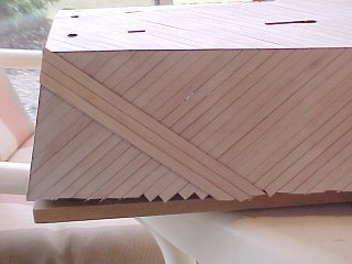
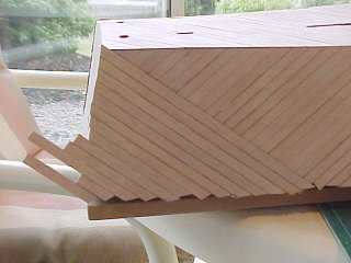
As you get further aft it becomes apparent that sanding the first side planking off to the keel angle is not going to work on the aft end due to the shallow angles involved so after about the rib25 position I started sawing the planks through using a pencil line and a hobby saw and then using the remaining plank half on the other bottom side, if sawn through carefully the resulting butt join is a perfect angle
Forward of rib25 sand the planking off to the keel shape and overlap the keel join.
As you pass the various keel cutouts for propshafts and rudders etc. cut smaller holes out of the planking so that you know where they are later. Cut the propshaft holes more to stern than you think or they will be too far forward.
Once you have finished both sides and bottom planking, trim, file and sand all the edges to the hull shape. Don't round the edges, keep them really sharp, particularly the keel at the bow as we have to put on more planking yet. I filed off one flat side of a cork sanding block as a progressive curve and then super-glued some fairly rough sandpaper to it to make a sanding block a similar shape to the bow shape. I am really pleased with this hull!
![]()
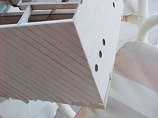
Once the transom is sanded apply planking really neatly, butt joined at the angle shown, There will be only one layer of planking here as there is no need for two layers due to the solid waterproof transom. Cut out the exhaust pipe holes as you go with a scalpel, little cuts at a time.
Layer Two
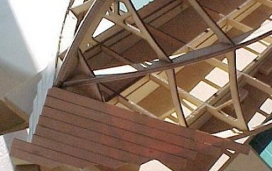
Once the bottom and transom are covered with one layer of planking and sanded off start on layer two on the sides. Start at the rear full length and work back to the transom and then plank forwards. I chose the plank angle based on a couple of pictures that I have in books and the movie "Giant Killers", which is a movie of the Elco boat construction in 1943, and it is also based on each full strip being about half the length (~ 200mm) of the laser cut strips that I made so that there is very little wastage. This comes out very close to the original boat planking angle. Run a line of glue down the edge of the last plank and another line just in from where the new plank will end and along the chine join line.
This is the bow with both sides double planked, the planking angle is not bad but if the strips were longer it would have been more accurate at the bow.
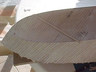
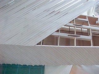
Once the sides are sanded off to the chine edge you can start on the second layer of bottom planking, again I started with a "half' length of planking (~200mm) near the bow and I will plank to the bow and then to the stern.
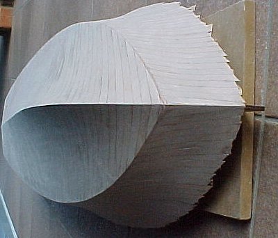
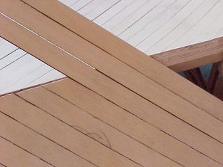
This is the hull all double planked with just a light sand.
There are approximately 110 strips per surface and 25 strips on the transom so all up there are in excess of 900 strips of planking and 2 x 2oz bottles of "Flash" medium cyanoacrylate super glue (NHP 322)..
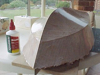
In order to fill up most of the gaps between the planks and re-glue the odd strip that was a little loose on one side I made up a very thin 50-50 solution of PVA wood glue and water and painted the whole surface of the hull, this solution soaks right in between the strips of wood, I then made up a slightly thicker solution and painted it twice more, about a day apart to let the previous coat dry fully. Once dry the hull can be sanded again and then painted. I will probably paint this hull 'Forest Green' as I intend to make it into PT109. I want to leave some evidence of the planking so I don't want the surface perfectly smooth, I want to be able to see the plank joins but it does need to be waterproof obviously! If you want a more smooth finish you could mix some sanding sawdust in with the final PVA solution which will act as a filler.
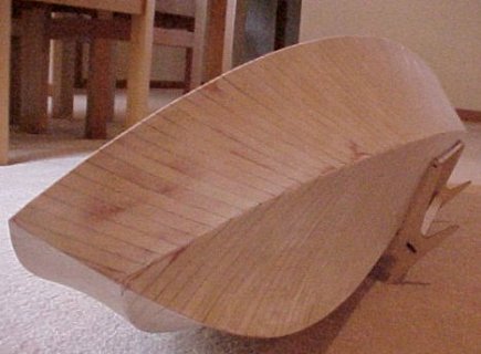
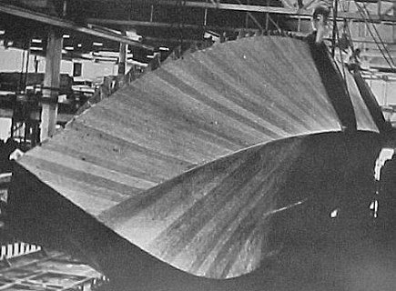
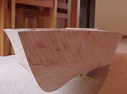
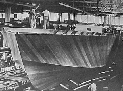

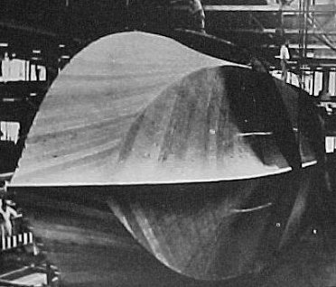
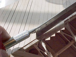
This is the hull filled and sanded and removed from the assembly board (left, in my dining room) compared to pictures of the original hull (right, in Elco's Factory) from Victor Chun's book and I have tried real hard to get the perspective, angles and lighting the same. Based on these comparisons I reckon the original planking was probably 5" wide and not 6" wide. I trimmed up the side planking around the deck level with a thin cutting blade in a "Dremel" and then sanded flush with the rib tops. An advantage of laser cutting is that it leaves the edges brown so you can see you've sanded.
So if I look at the second layer of planking on my model on the left, the angle of the planking could have been a bit steeper in order to match the original Hull, on the right, so, if I measure the side planking on my model at the stern and I start at where the chine meets the stern, the side planking slopes up and towards the bow and meets the deck around 135mm forward of the stern. If I measure the bottom planking, again at the stern, and I start at where the chine meets the stern, the bottom planking slopes towards the keel and towards the bow and meets the keel around 110mm forward of the stern.
So in retrospect I reckon that these distances need to be at least 150mm (6") (or maybe even 7") and 125mm (5") (maybe even 6") to make it look like the original ww2 Hull. I hope that is understandable?
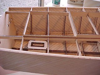
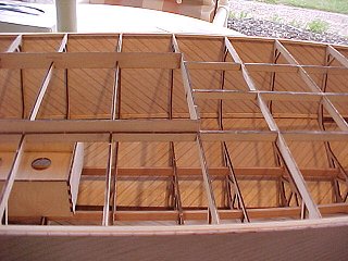
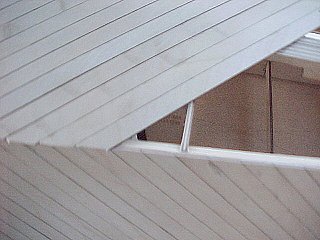
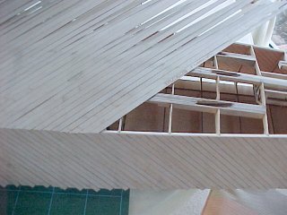
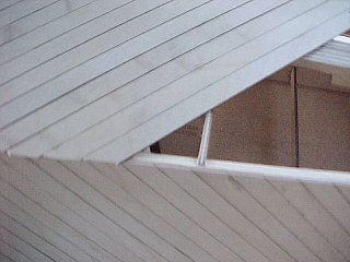
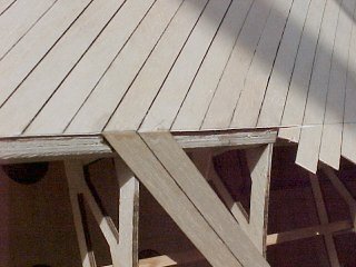
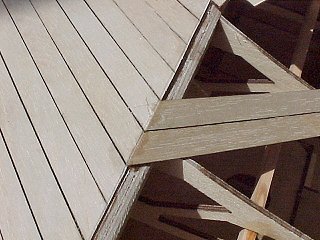
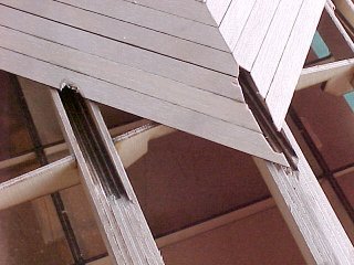
These two pictures show the building runners stripped off leaving the upstand section through the center of the boat, the decking will go around the upstand which is there to provide a base to hold the superstructure on and to stop water getting into the hull when underway.
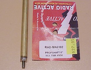
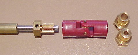
This is the 8" propshaft and the universal couplings that I will be using in the 1/20th scale Hull-2, the brass parts of the couplings are available in every size you might need to suit any motor or propshaft size, shown here are 4mm, 5mm and 3.18mm (1/8") I believe these are available all over the world and are branded as "Radio Active" in Australia.
Prop shafts, new cast struts and cast rudders fitted, there will be three more struts further up the shafts, fitted later. I cut the prop shaft outer tubes down to 110mm (4.33") long, drove out the bearing from the short left over end using the blunt end of a drill bit that just fitted the inside of the tube and pressed it into the new shorter tube. I was going to mount them with the propshaft tube ends sticking out of the boat with square cut ends and not fit the extra struts but then decided that that would look crap, so I then pushed the bearings further up the tubes and cut the tubes at an angle to match the hull openings so that the brass tube would be flush with the hull, easier than I thought actually. I then fitted the struts and tubes one at a time using Araldite and inserted a long piece of 4mm diameter stainless steel piano wire to line up the strut, shaft tube and through the motor mount to keep it all in line while the glue cured. The centre strut needed a little "fitting" into the hull as its angle with respect to the hull is very slightly different to the outside struts.
Make sure you don't epoxy the temporary 4mm shaft!!!
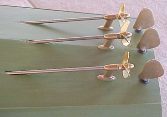
You may also notice that I have three different propellers fitted, two different shape 35mm types and a 40mm, all Raboesch, I have fitted them with a locknut as they are all left hand propellers but once I have decided on the type to use I will use an anaerobic glue to lock them on to the shafts and get rid of the nut as it just doesn't look right.
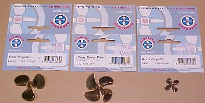
I have bought some new 40mm props, two more of the 156-06 which is the closest shape to the original boat, a 4 bladed type which Raboesch recommend for fast boats which is a RH type as I want to try the center prop rotating in the opposite direction to the outside props and I also found a cute little 4 bladed 20mm prop for the 1/35th Hull-2 model which has an M3 thread, there is also a 3 bladed version but the blade area looked a bit tiny so I will try three of these first!
The hull covering has been slightly countersunk and then re-painted at the rudder holes as the rudder tubes have O-rings that I wanted to keep in place better than just squashing them out of shape, particularly the middle one on the main keel..
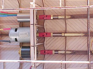
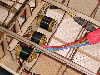
Test motors and universals fitted, three different motors, two brushless and one 700 size brush motor.
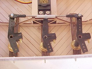
All three rudders fitted with tiller arms connected with universal couplings, threaded rod and a dual ball coupling at the centre arm. I still need to couple the servo to the rudder linkage and it would be really helpful if the tiller arms had a 'T" shape, I may have to make up something as I did in boat-1.
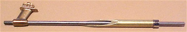
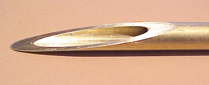
A drawing and photo's of the propshaft, I made mine from the 8" long "Radio Active" ones that I bought (photo does not show the correct length, just a trial). The brass tube MUST come out through the hull planking so the opening can be sealed properly, from a sanding and finishing perspective the brass is probably easier to sand than the birch ply, so it can be sanded flush or you can fill the gap if it is slightly below the surface. The centre tube needs to be filed to an angle on each side to make the shape of the keel.
17th June 2005 --- Hull-2 In the pool with 3 AXI Brushless motors
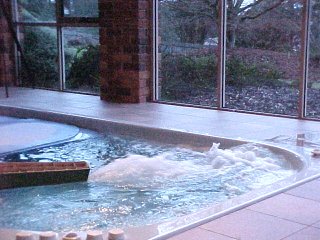
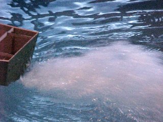
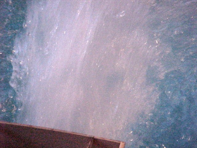
That's some serious water

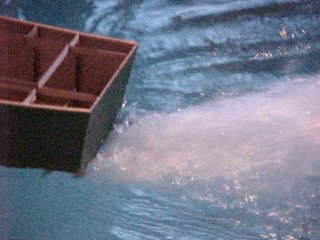
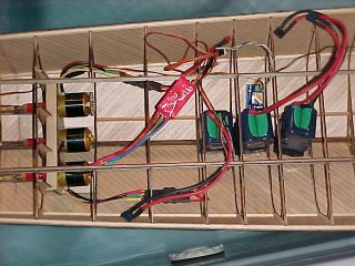
These shots are with three AXI 2820-10 brushless motors, two 40mm 3 blade LH props and one 40mm 4 blade RH prop, two Jia Bao 40A brushless controllers and one Kontronic 40A controller, so no reverse yet.
I am very pleased, this boat is very hard to hold and I have a feeling it is going to go like a bat out of hell!!! That rooster tail is twice as high as the boat and it took me a while to mop up the mess!
This is what made all the mess, I made a fan on one of the motors but they don't seem to get hot anyway!

Bob Koski sent me a picture of his fully planked Hull-2 being thoroughly scrutinised by his marine inspector "Mippsey"
Bob is in the US and for covering he bought 0.8mm Finnish Birch Ply from "Aircraft Spruce and Specialties" and used a standard Balsa splitter with a #11 Exacto Blade to make the strips, he glued it with medium CA and also used an old mono-kote hot iron on medium heat to iron the ply into shape which he said relaxes the wood and allows it to fit easier and keeps much of the glue off your fingers.
Now the deck - to plank or not to plank? The Elco movie "Giant Killers" of the original construction shows a full half width, 80' length of scarf joined ply sheet being brought in by over a dozen men and laid down on the boats deck and then screwed into place with many thousands of screws but many photo's of the boat's deck's show lines like planking. Also there is a picture in Victor Chun's book that seems to show planking on an 80' boat. Was the deck planked over the ply maybe?