Schnellboot 1/20th Scale Hull
(for the German S-100 Class Schnellboot (Fast Boat))
I will be separating the various scale hulls as they are diverging due to material sizes - I am also working on a 1/30th scale
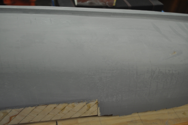
I have painted the hull with a thick automotive prep paint, it's supposed to be sprayed on but I found that a paintbrush works just as well except that it dries really fast. This stuff is easy to sand also and fills all the gaps.
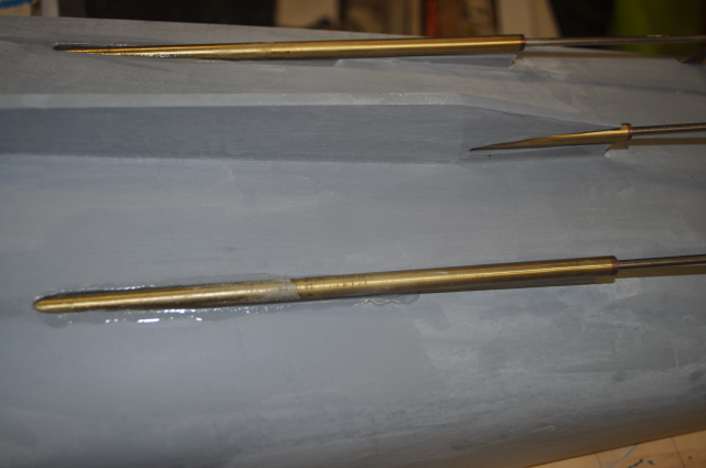
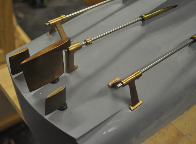
I have installed the propeller shafts and the struts. These are superglued from the outside. I will need to use some filler and a bit of sanding around the tubes.
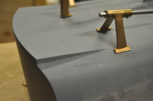
Cast silicon bronze struts fitted in place, I used Loctite brand superglue on the mountings and I will add some epoxy from the inside around the mounting tabs to add strength and waterproofing. I needed to file a slot in the mounting tabs of the two wing struts to clear the rib above.
This picture also gives a good view of the port side of the "step" which I added later using epoxy filling compound. Unfortunately I can't find the pictures that I took when making it but it was quite easy to make, I glued a strip of thin ply to the stern, over the paint, following the curve and two more triangular pieces between it and the hull bottom going forwards and then poured epoxy filling compound into the shape and let it set and then removed the ply bits and sanded it back and re-painted it. I thought about building this into the hull frame but I decided it would be too hard to maintain the curve of the side planking towards the stern and doing it later makes it adjustable. The reason it's there is to stop the stern from digging in at speed, many high performance boats have something like this and sometimes it's hydraulic and adjustable, the American PT boats played with what they called "slippers".
It is important to make sure that the shafts and struts are all lined up as carefully as possible so there is no bending of the shafts as they rotate as this will cause shuddering and wear. The shaft tubes also need to be stuffed with grease before final assembly for wear and to stop water penetration into the hull.
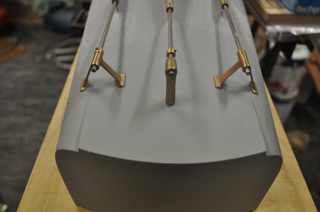
![]()
Shafts and struts from the stern view.
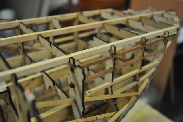
At last I have the Schnellboot hull free from the building board and up the right way.
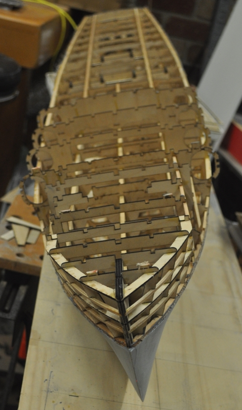
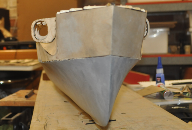
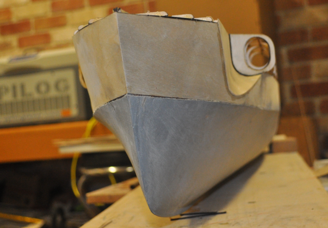
This view shows the bow. I haven't finished the forecastle covering as I need to make sure the torpedo door is in the right place and is the right angle which can't really be done upside down.
Cutting it loose from the building board was easier than I thought it would be.
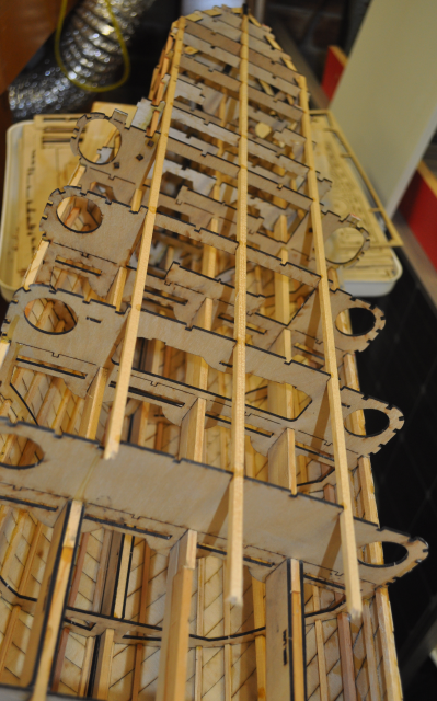
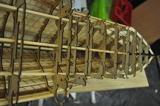
I have inserted three runners at the top of the forecastle.
The rudder holes have been filled with the Builders 2 part epoxy putty that I used to build the "step" at the stern.
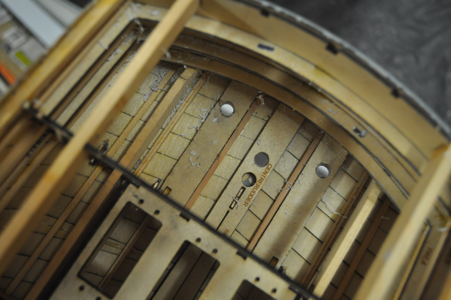
I drilled the holes out from the inside of the hull to get them lined up in the right spot with a small drill and then drilled from the outside with progressively larger drills.
You can also see the tops of the struts in this view, I used Loctite superglue to put them in but I will run some epoxy from the inside to make sure they are held tight and waterproof, I will also run some epoxy into the keel to seal around the propshafts.
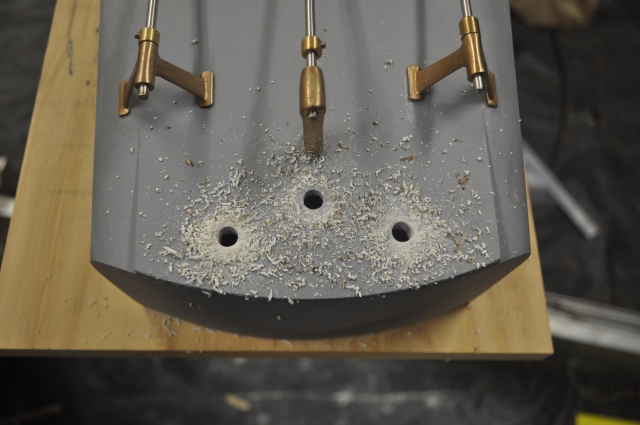
I finished drilling them 8mm diameter to suit the rudder shafts that I have.
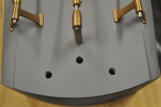
Ready to put in the rudder tubes.
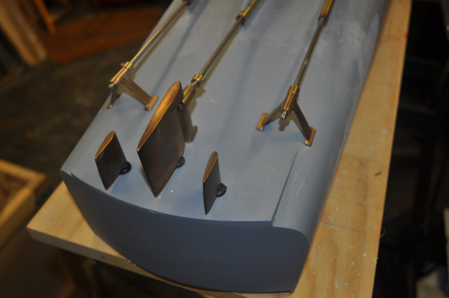
Rudder tubes and rudders in place.
Rudders from the port side. The centre rudder is leaning rearwards a bit so I packed the inside forward of the rudder tube with some thin ply before tightening the lock nut that holds it in place, this helps tilt the rudder forward towards the strut a little.
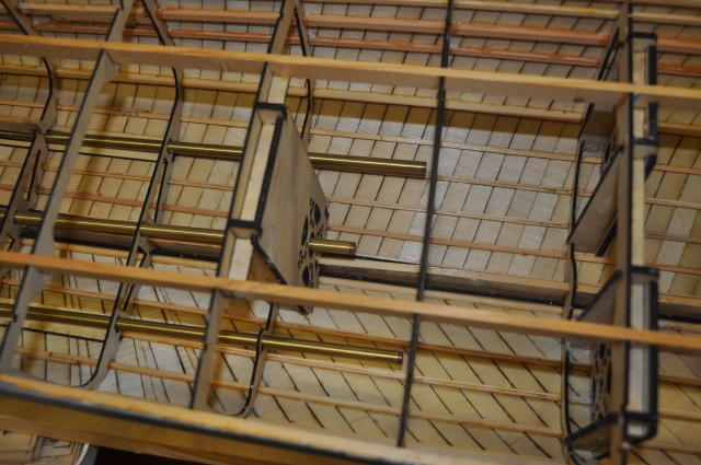
I have some issues with the propshafts that I purchased as the two outside shaft tubes are a little too short to reach the last rib (rib 8) before the motor mount and they are a little too small in diameter than I allowed for and wobble around in the holes in the ribs, so I added some brass tubes to extend them and make them a little fatter. The middle prop tube is also too long for where I initially fitted the centre motor mount but I have also made a motor mount to fit on the next rib forward (rib 8), which is now part of the rib kit, so I will fit that and leave the other one in place as it supports the end of the shaft tube.
In this picture you can see the propshaft extensions on the two outer tubes between ribs 8 and 9.
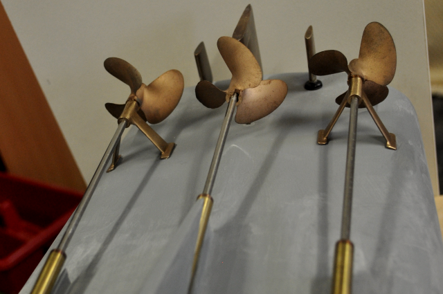
This shows the full set - propshafts, my cast silicon bronze struts, Octura brand props and my cast silicon bronze rudders. The props are "dog" drive props as you can see on the centre one so I will need to get some dog drive collets to fit on the 4mm diameter shafts forward of the props.
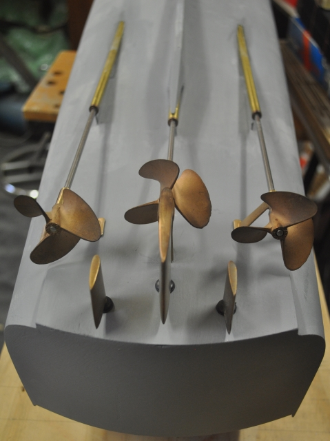
The full set from astern, I need to make or buy some tapered prop extensions for the two outside props to make them look right.
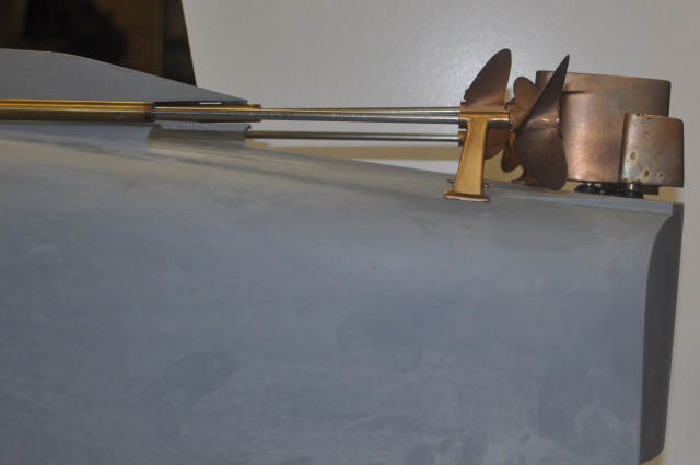
The full set from the starboard side. The prop shafts that came with the propshaft tubes were too short so I purchased some 4mm diameter 1810 stainless steel rod and made new ones, this was surprisingly cheap $5.00 for a 3 metre length. If I started again I would use a 5mm shaft but I would have to make up the shaft tubes and bearings.
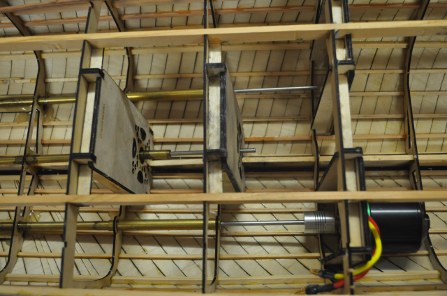
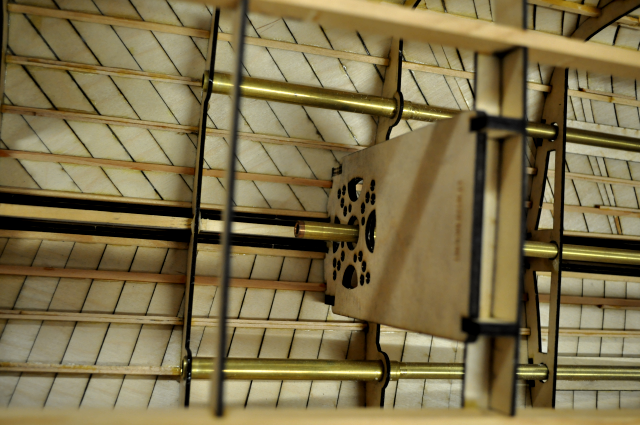
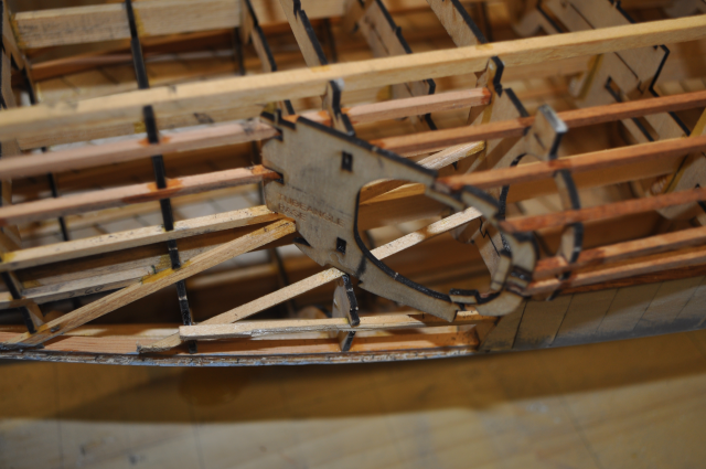
This shows the Rib8 centre motor mount added forward of the Rib7 motor mount.
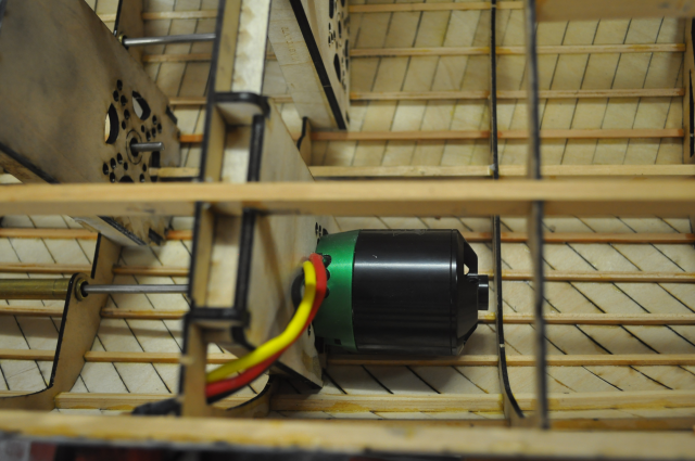
This is another view of the Rib 8 motor mount.
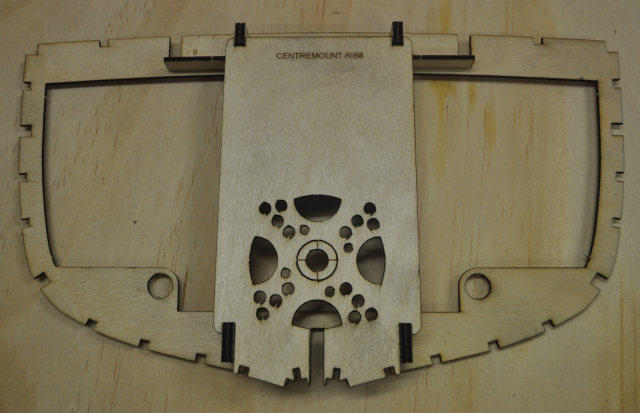
This shows the Rib8 centre motor mount assembly.
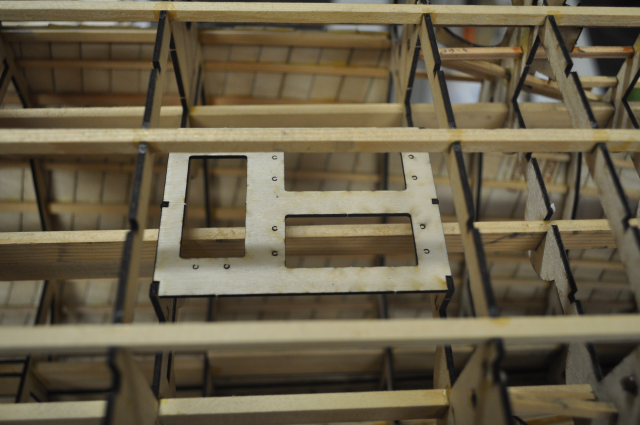
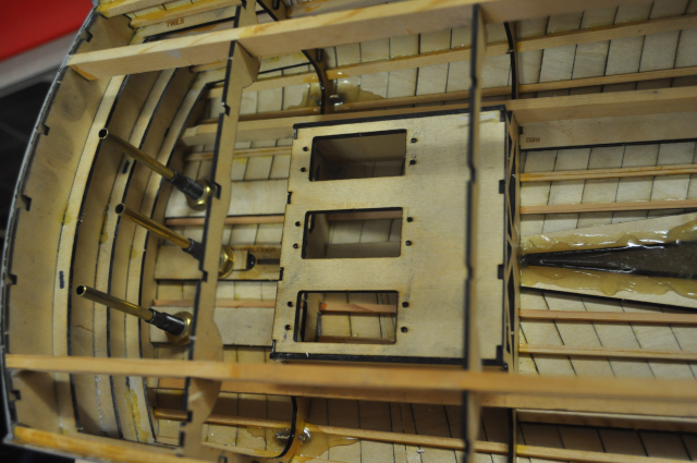
I did a new servo mount for the forward location, the intent is to use it for the torpedo doors and the forward deck cannon. I fitted three large servo's but the rear (left hand) location isn't deep enough due to the cemtre spar below, I might rethink this and use 4 small servos instead.
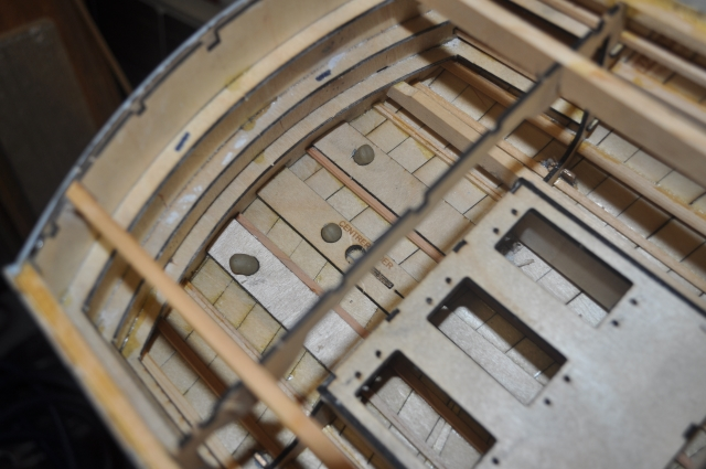
I have filled the centre keel with two part epoxy as well as the wing propshaft openings and the tops of the struts, this adds some strength and waterproofing.
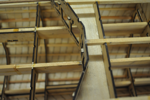
There is a horizontal spacer (Rib13C) that fits onto rib 13B that in turn supports three small extra sections Rib13D, E and F, this then forms the front support for the armoured Kallotte. The rear of the torpedo tubes also fits through this.
Same again from aft viewpoint
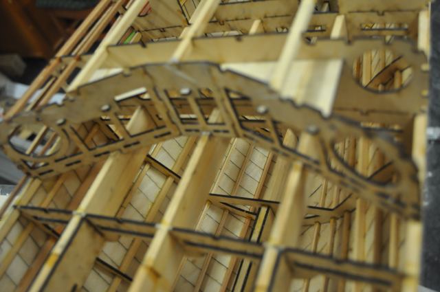
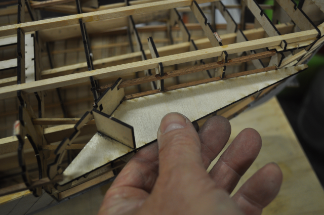
This view shows the runners in the torpedo tube hull cutout area and also shows a couple of notches on the rib where the 45 degree torpedo door opening frame fits.
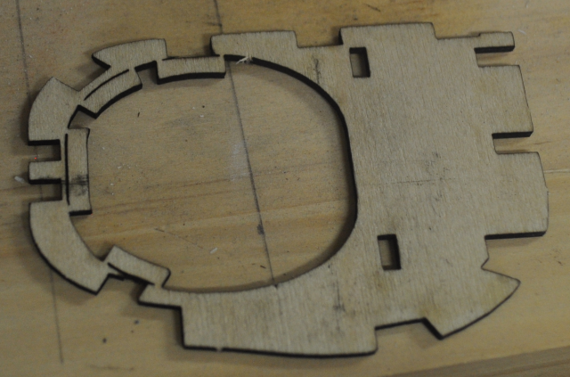
This is the tube door opening frame, this was a real turd of a piece to get right, again you can see two holes that fit over the notches in the previos photo.
The frame sits at a 45 degree angle relative to the centreline of the boat, so getting it right is an issue as nothing will fit from here on if it isn't in the right place or at the right angle!
I made up an alignment tool to get the angle right, horizontally and vertically before gluing the frames in place.
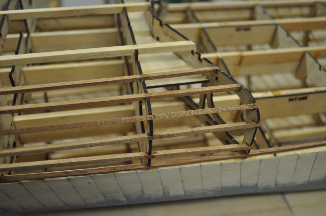
Once the tube door frame and the extra parts of Rib13 are in place the tube covering frame can be finished off with 6 (3mmx3mm) runners. The bottom runner twists along it's length so I glued it in place at the tube door frame and the frame aft of it and then waited for the glue to dry, then I twisted the uncut runner and tucked it into one of the deck cutouts designe for the same size material before gluing the runner at every rearward frame.
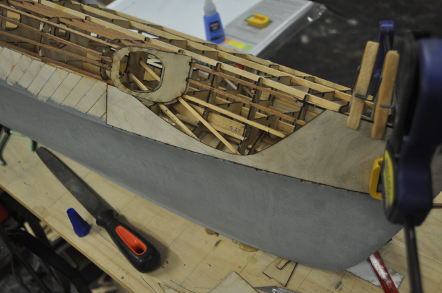
OK lets start on the forecastle covering, you have no idea how many trials I went through in cardboard to get the shape right, however it fits really well now, except the curve is a compound shape so I had to peg the upper section while the superglue dried. I may change this and do two levels to make it easier although it's probably better to leave it. This is the inner layer and can be covered with strips on the outer layer, I needed this piece to make the boundary for the torpedo cutout to glue to. I have actually glued the other side cutout already without the forecastle covering and it didn't go all that well.
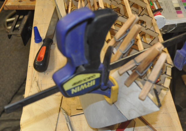
As you can see I used a few pegs to get the top edge to stay in place and a clamp to get the bottom edge right.
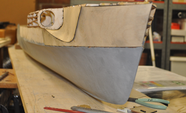
Ta Dah! starting to look like a Schnellboot now, It's taken me three weeks to get this section complete even though the basic design was done many years ago.
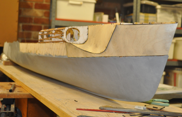
I'm impressed with my own handiwork here!
Both sides of the forecastle covered
From the front port side.
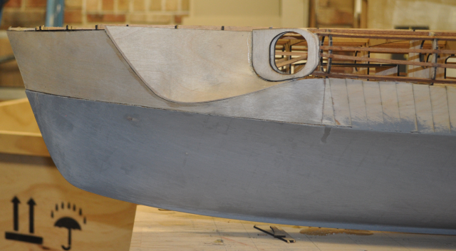
From the port side.
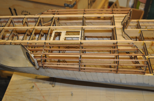
Torpedo tube covering under structure.