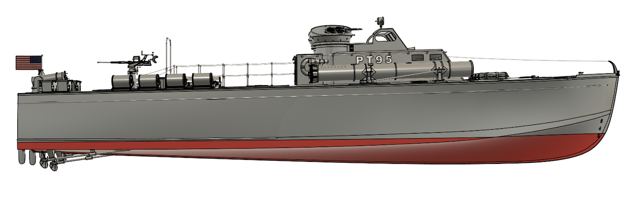
Huckins 78' (PT-95) 20th scale PT Boat Hull
Having completed the Vosper Hull I decided to do a 20th scale Huckins Hull.
I find the Huckins to be the ugly duckling of the three US PT's, very utilitarian in design, not nearly as elegant as the Elco but it was, by all accounts, the best riding boat and should have become more popular, I guess we'll never know why things turned out the way they did for Huckins but seems when you mix military and money some strange things happen!
In the 20th scale Hull I am allowing for three electric motors of up to 35mm motors the same size as used in the Elco 20th scale.
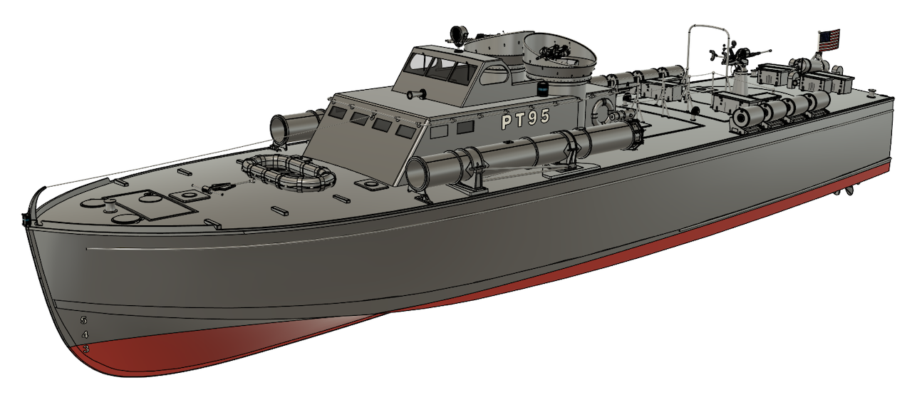
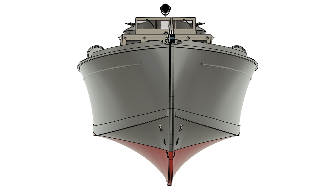
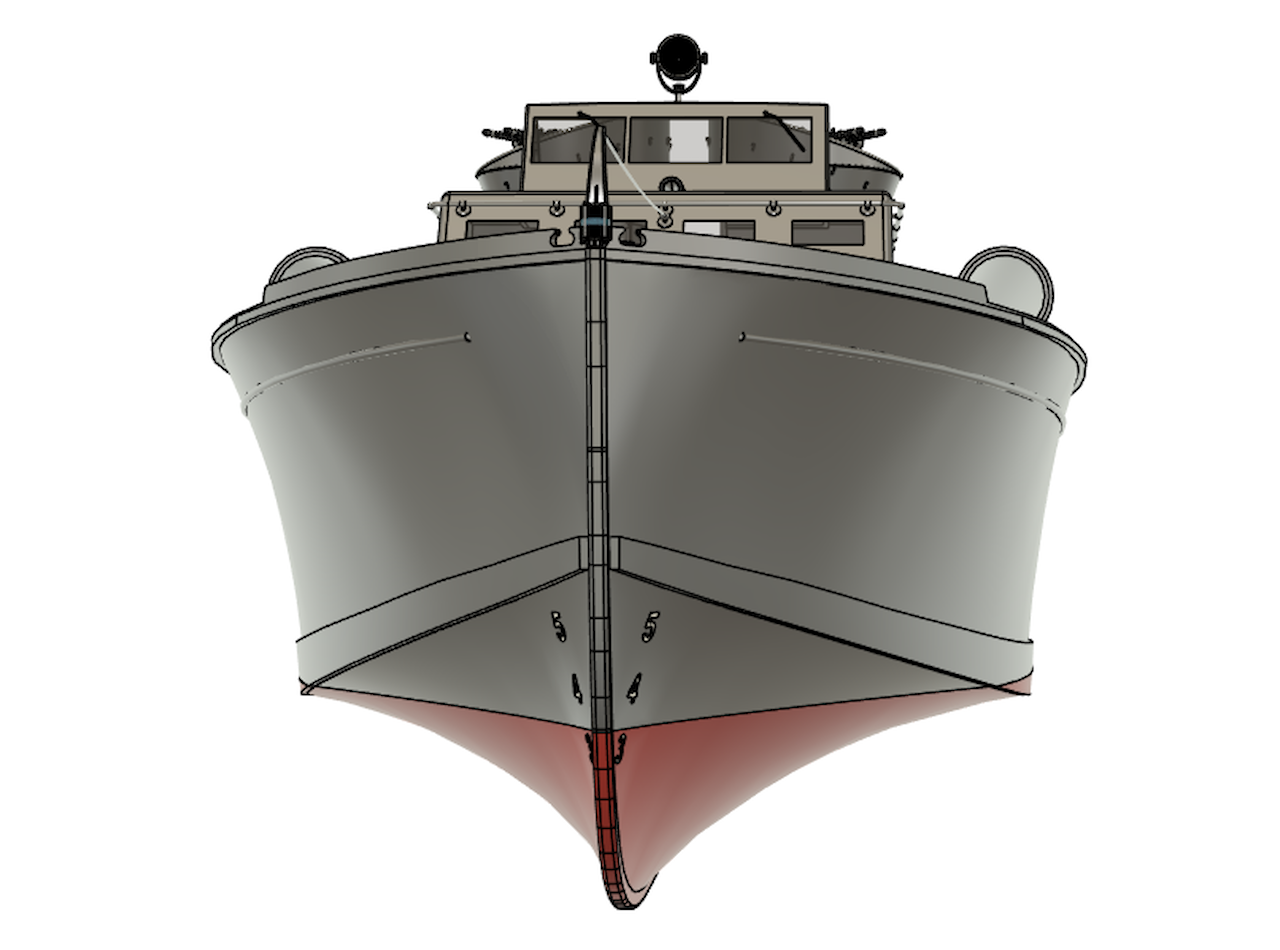
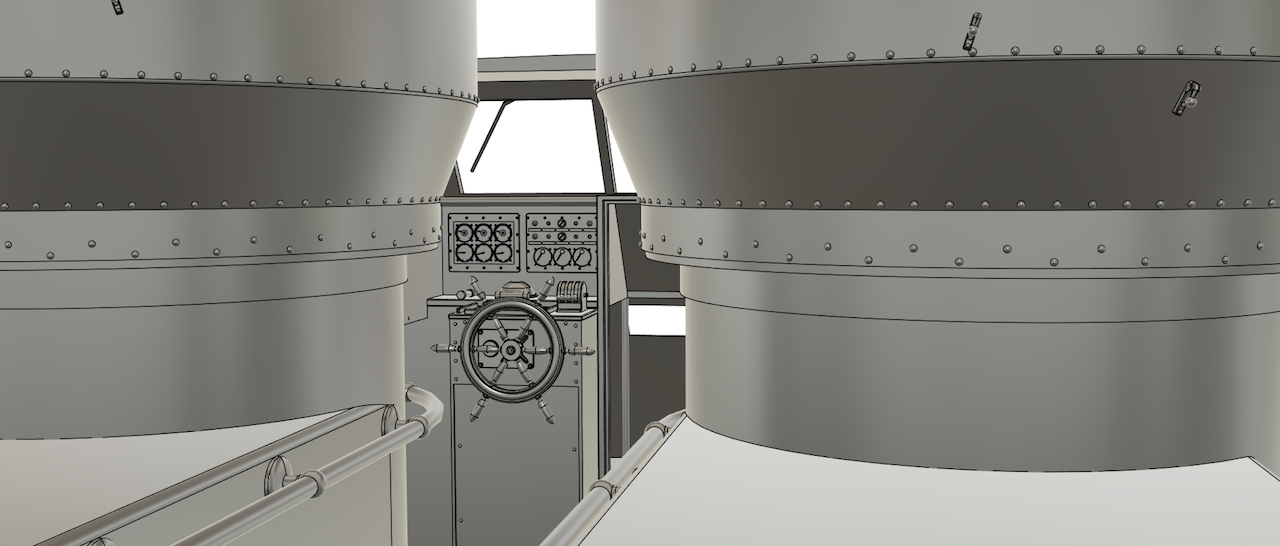
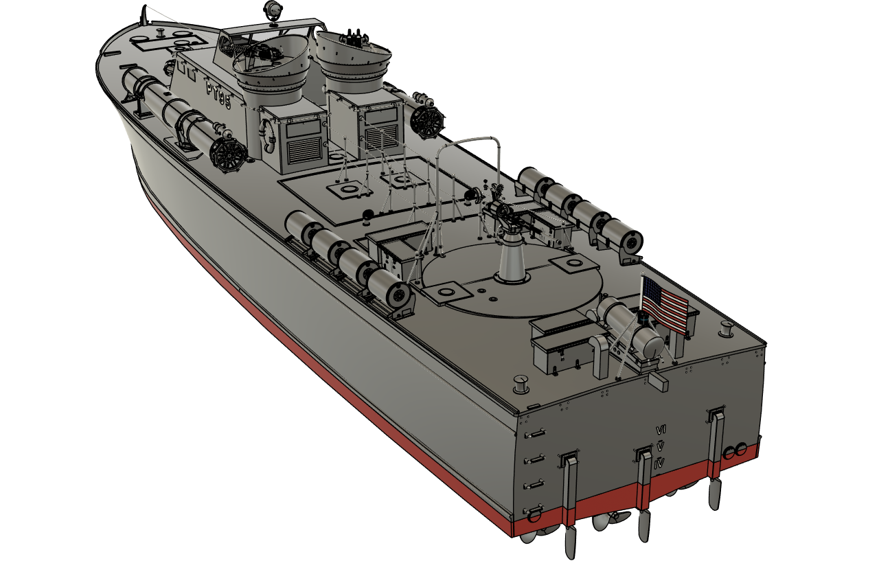
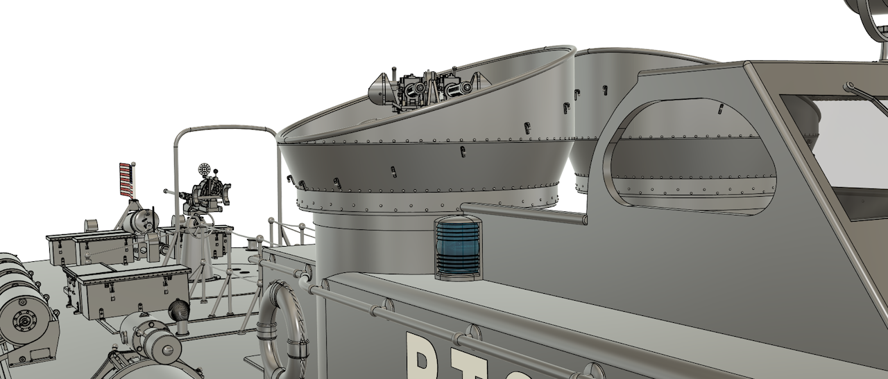
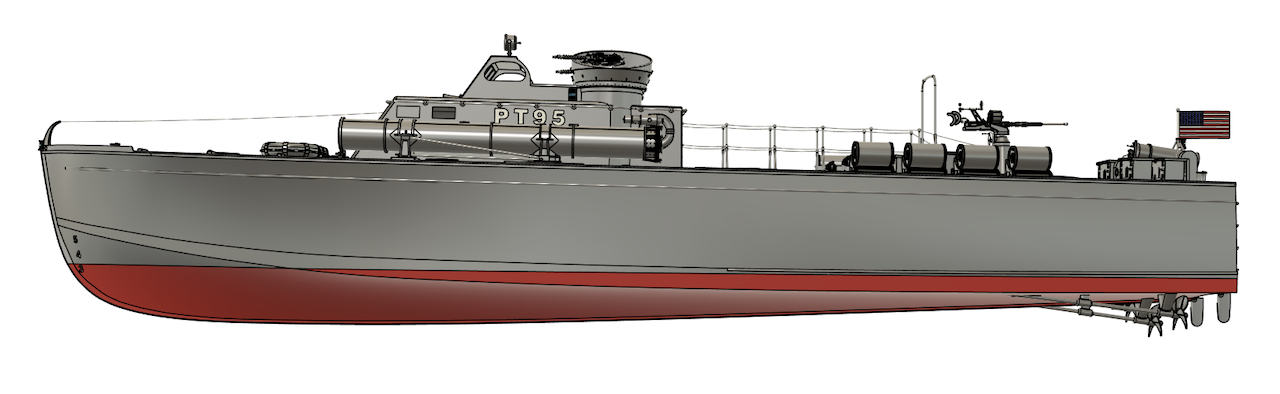
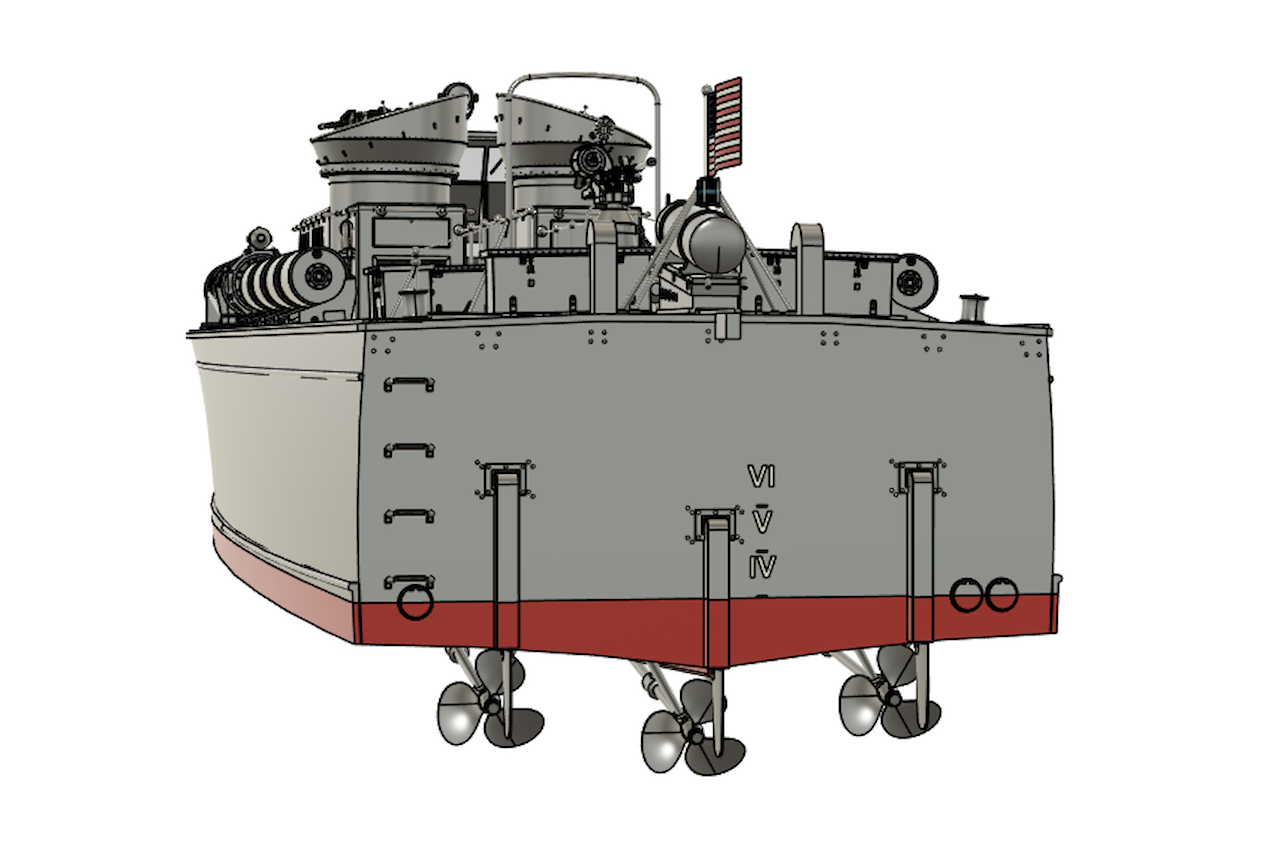
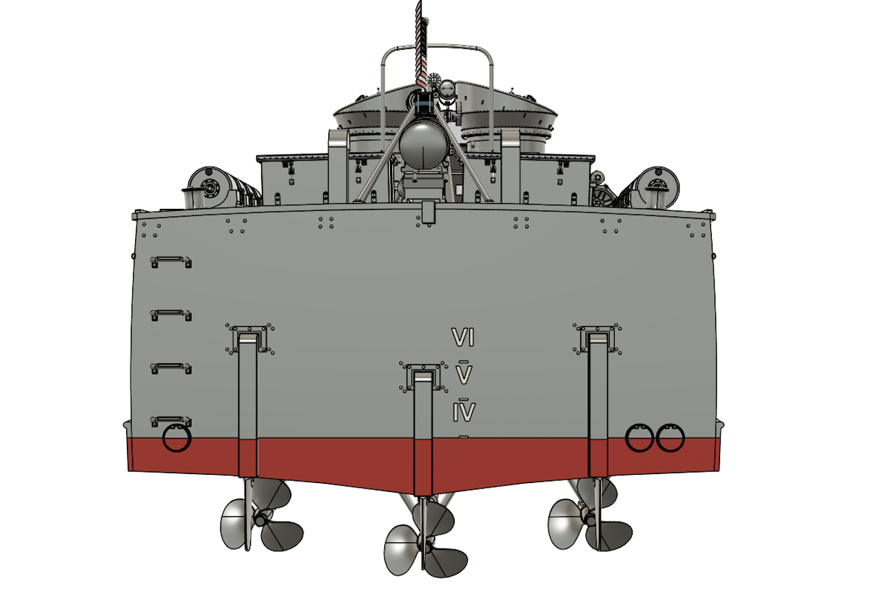
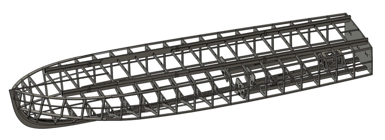
The images below are from my 3D model, produced in Autodesk Fusion (formerly Fusion 360) essentially completed (never say never) in September 2024. I have posed many of these images, as best I can, to mirror the various available historical photo's, not that there are a lot available!
There are essentially no historical drawings available for this boat, or the other 17 Huckins PT's (some say they were deliberately destroyed) so I am reliant on the one drawing of the experimental 82' boat (available from Huckins) and the few available on-line photo's and a few expert opinions such as Andy Small and Frank Andruss.
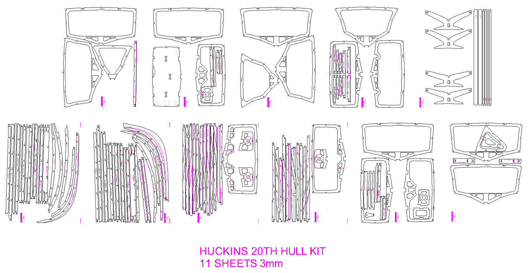
I will continue working on this boat as I want to produce a set of plans for it, from what we do know and I will produce a slightly different version with the later open bridge setup, roll off racks, radar etc. but first I will produce a laser cutting template set for a hull kit and a deck and superstructure kit.
With the Vosper model, I exported the ribs back out of the 3D model into Autocad and then produced the laser cutting outlines, which worked out perfectly smooth and accurate, so I will do the same with this model.
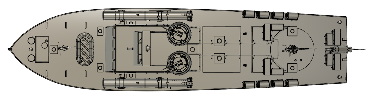
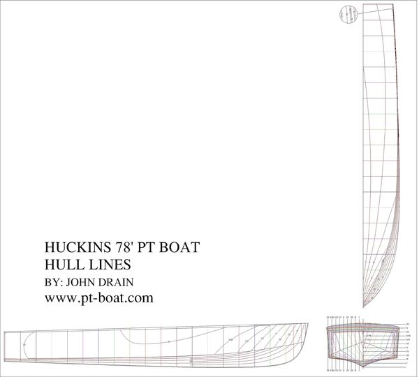
This is my version of the Huckins Hull "lines" which are sections through the (model) Hull at 1' sections both horizontally and vertically.
These lines are for the Rib profiles excluding the thickness of the hull skin, which in this case is 1.6mm or two layers of 0.8mm.
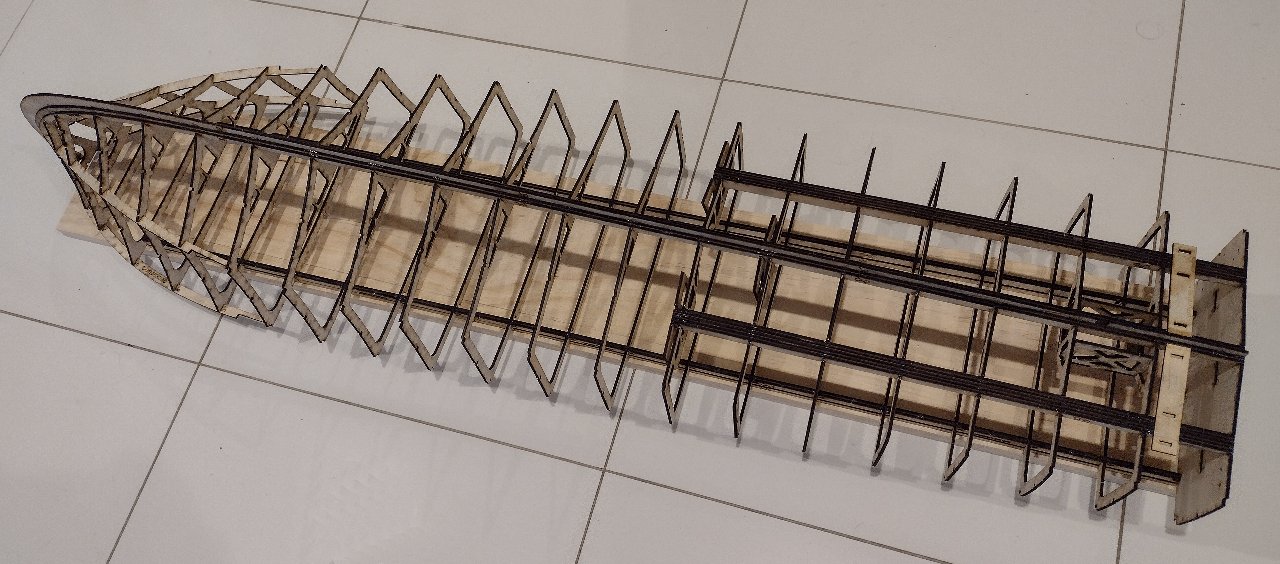
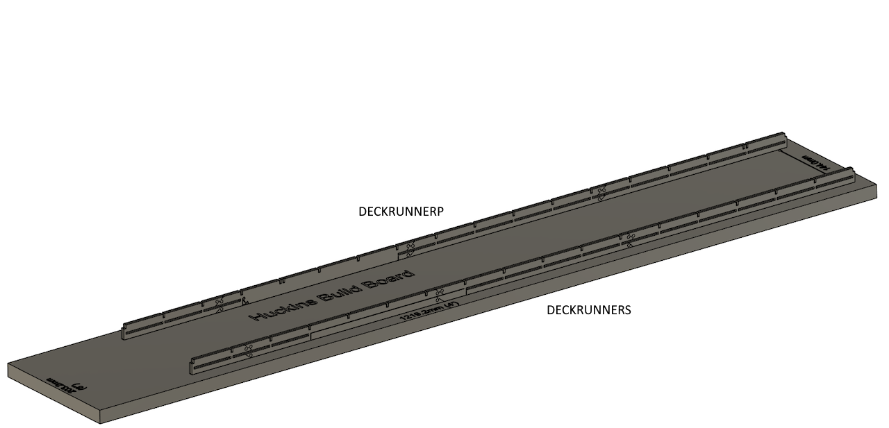
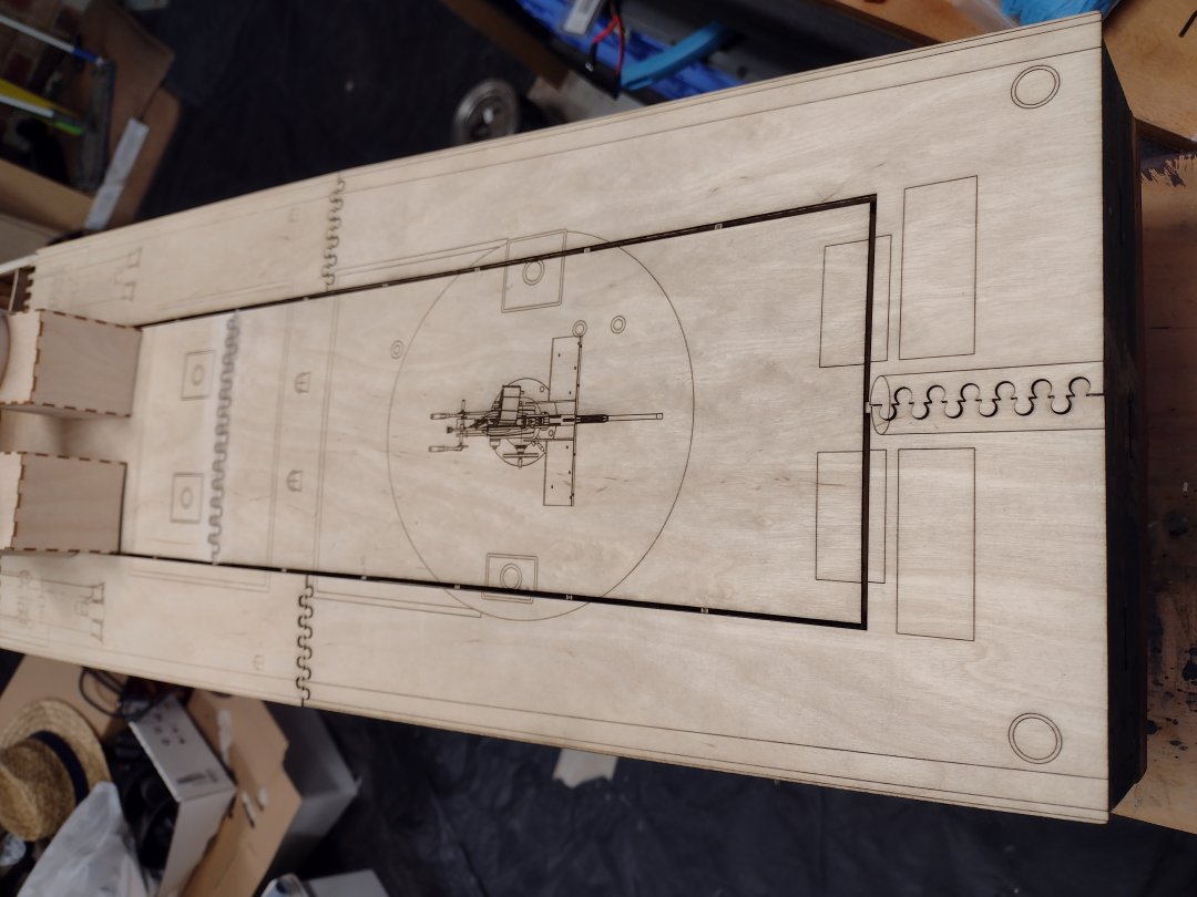
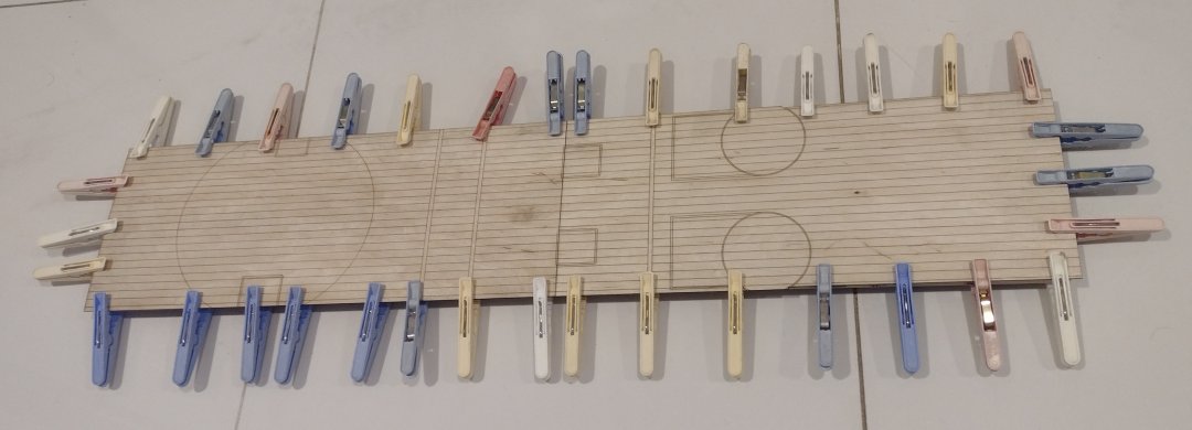
The Laser Cut Huckins 20th scale hull kit.

The ruler in the hull kit is 144mm long and that is the distance between the inside faces of the Deck runners that are glued to the build board, these runners need to be spaced accurately and absolutely straight and square to each other or the hull will end up twisted and the deck won't fit correctly, so that's why the square is there!
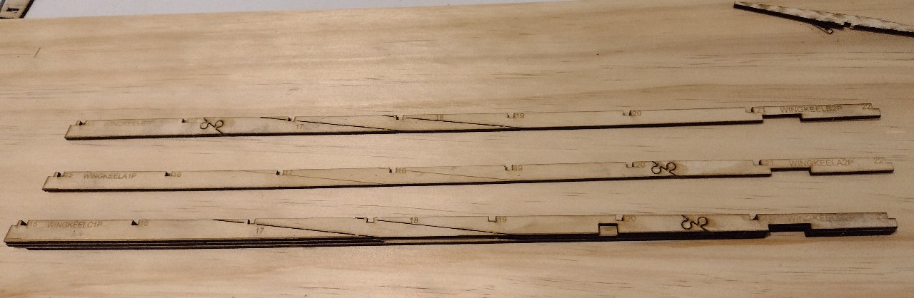
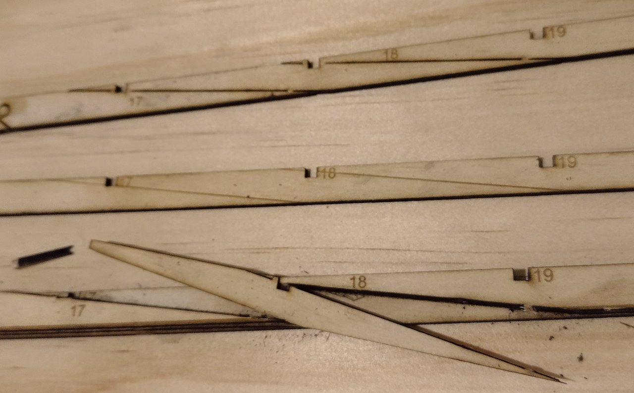
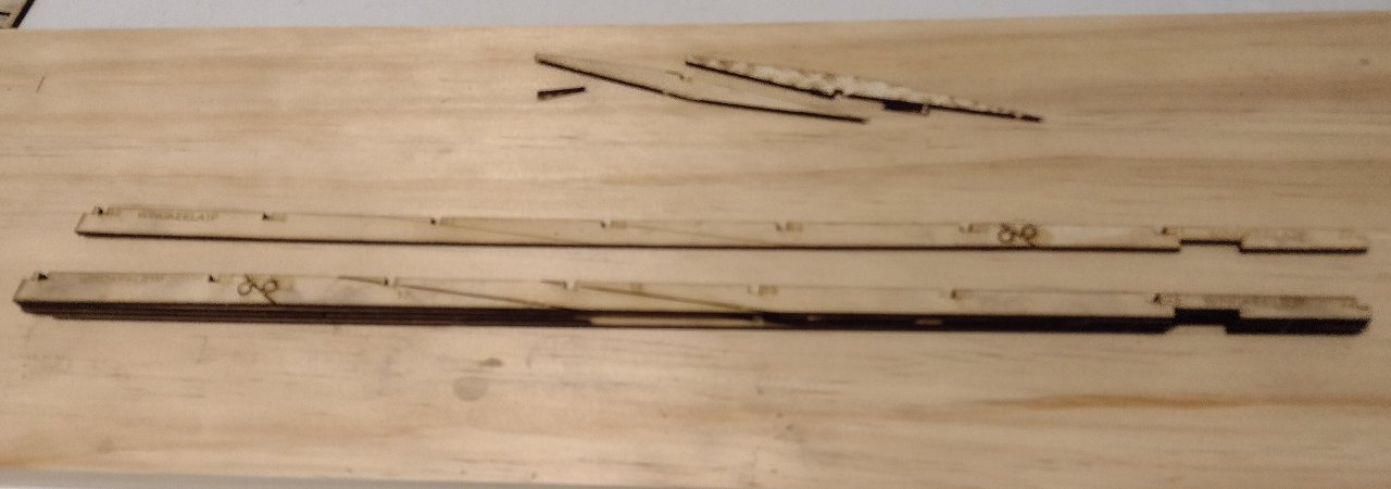
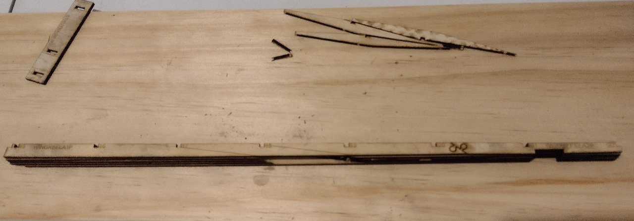
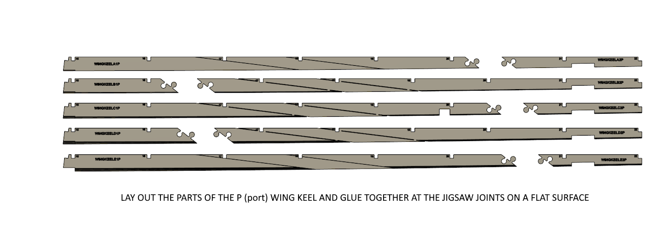
The series of pictures below show the process of how to make up the port and starboard wing keels.
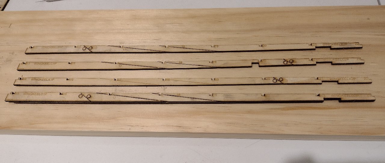
Glue all keels, part 1, to keels, part 2, at the jigsaw scarf joins (makes 5 pieces for the (P)ort side and 5 pieces for the (S)tbd side.)
You need to make sure the keel stays straight and square (on the top side) and lays flat on the cutting board.
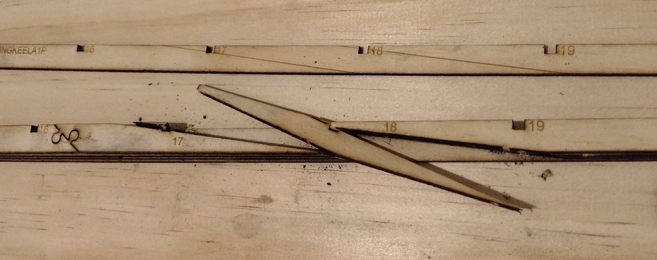
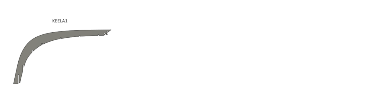
Then start with keel E on a flat surface and glue keel D on top (with no glue where the prop shaft angled section is, between ribs 17 and 18), line up the rib slots and make sure that the rib slot (upper) side is straight and square to the cutting board. The lower side is angled and gets smaller from keel E to keel A.
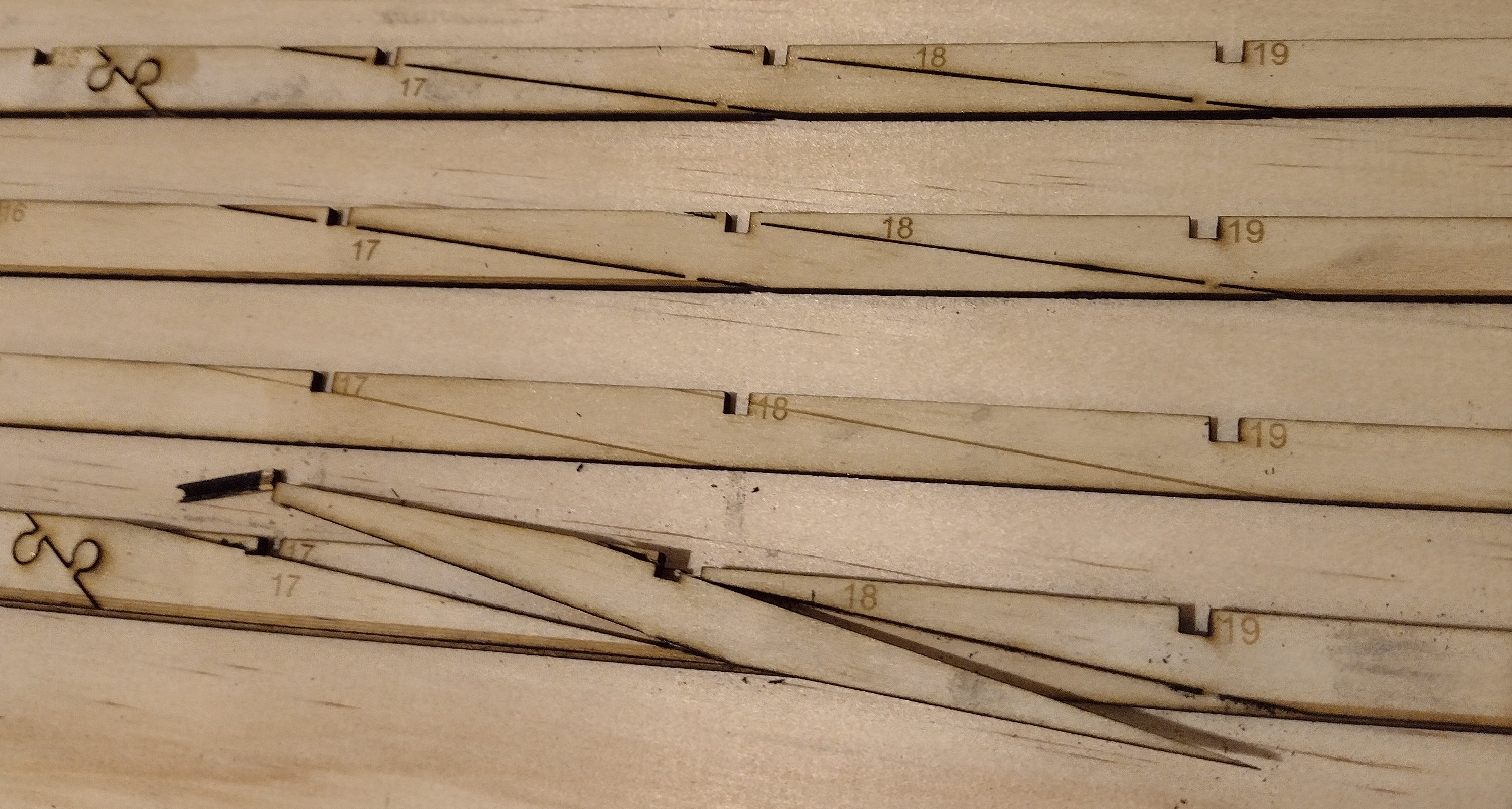
Cut out the angled propshaft area on keel D only, between ribs 17 and 18, take care not to cut into keel E.
Glue keel C on top of keel D and E (again, no glue where the angled prop shaft area is).
Cut out the prop shaft angled area on keel C only.
Glue keel B on top of keel C, D and E. (again with the no glue in the propshaft area!)
Cut out the prop shaft section on keel B only.
Glue keel A over the top of keel B, C, D and E. Make sure that the whole keel is straight and flat.
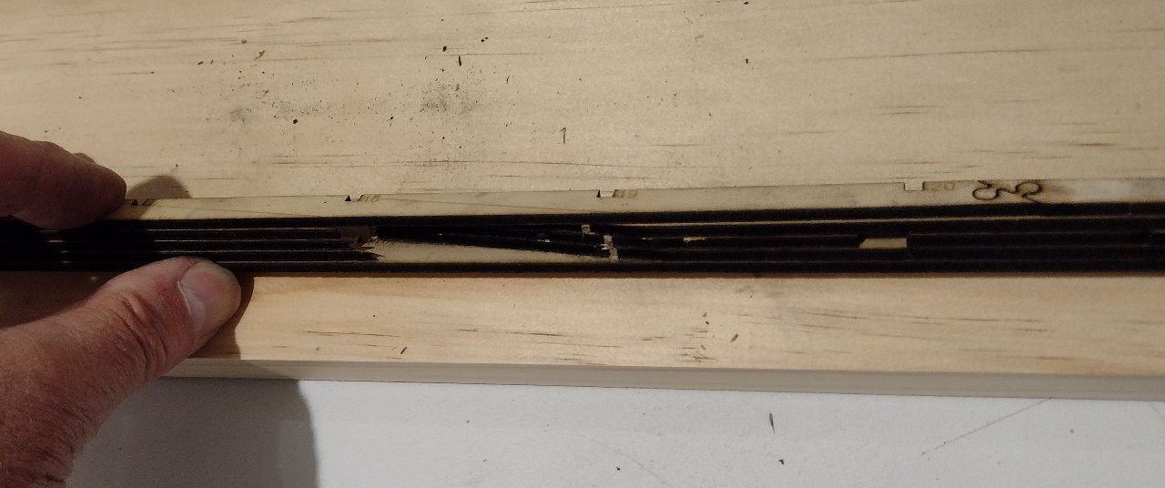
The finished prop shaft slot should look like this and will fit a 9mm diameter stuffing tube!
Click on the image above to see an animated movie of the assemby process for the Wing Keels.
Click on the image above to see an animated movie of the assembly process for the main keel.
Click on the image above to see an animated movie of the assembly process for the deck runners.
Click on the image above to see an animated movie of the assembly process for the complete hull frame.
Click on the image above to see an animated movie of the assembly process for the deck hatch frame.
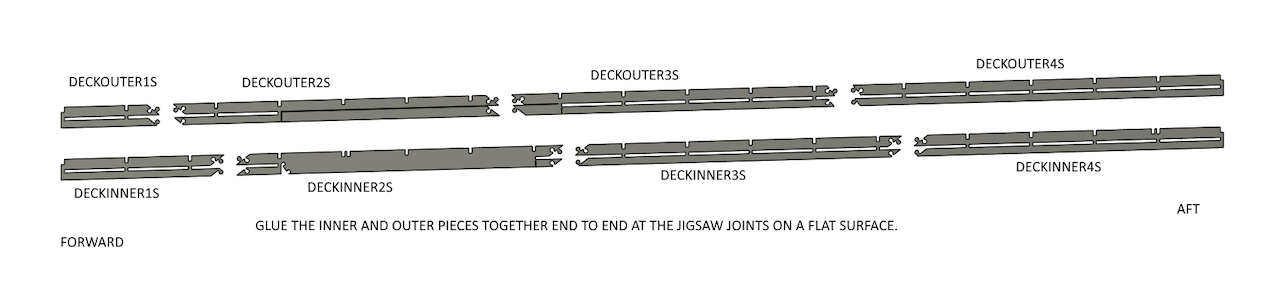
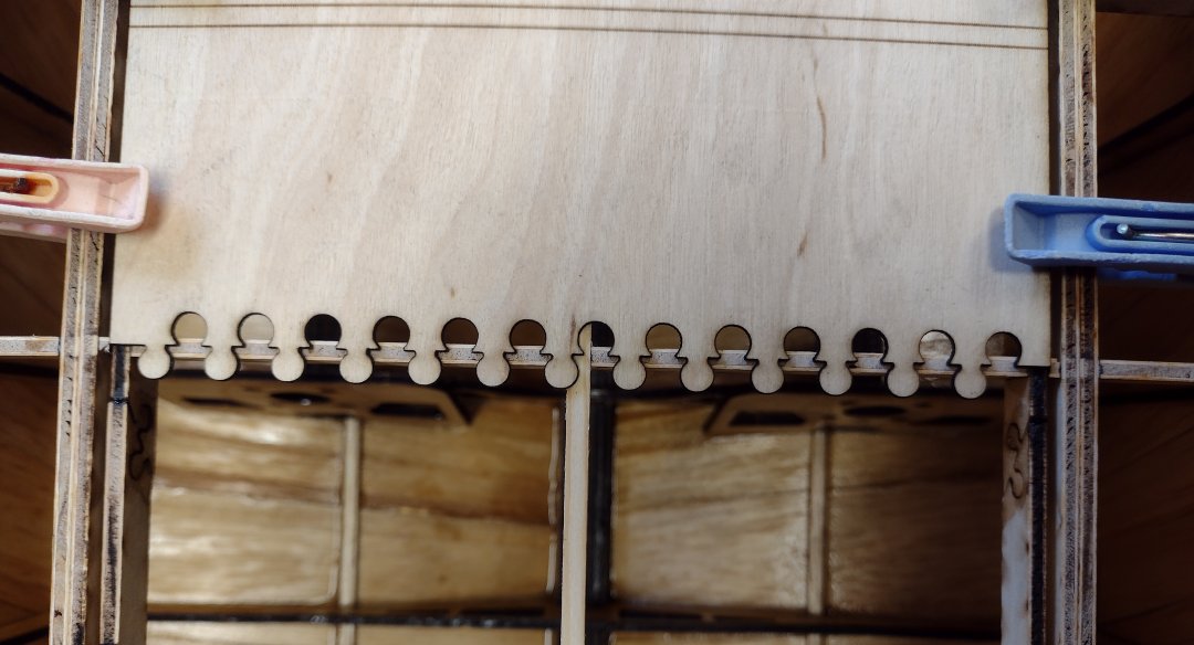
Once the hull kit is released from the cutting board (usually after the hull covering is done), the hatch frame needs to be made up as an integral part of the complete hull frame otherwise it will not fit correctly or will be twisted. The hatch frame needs to be covered with the first layer of the deck hatch (deck kit) covering and then the "tops" of the ribs can be cut through between the hatch frame outside and the deck runners with a fine hobby saw to release the hatch from the remainder of the hull deck.
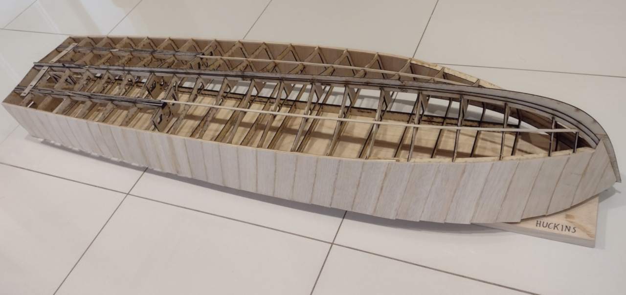
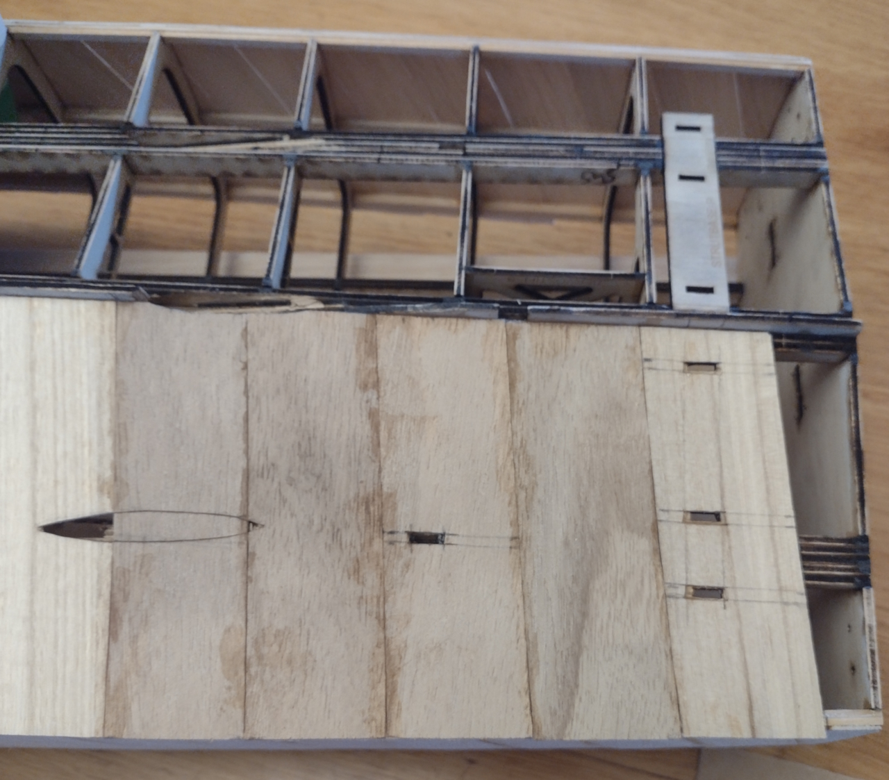
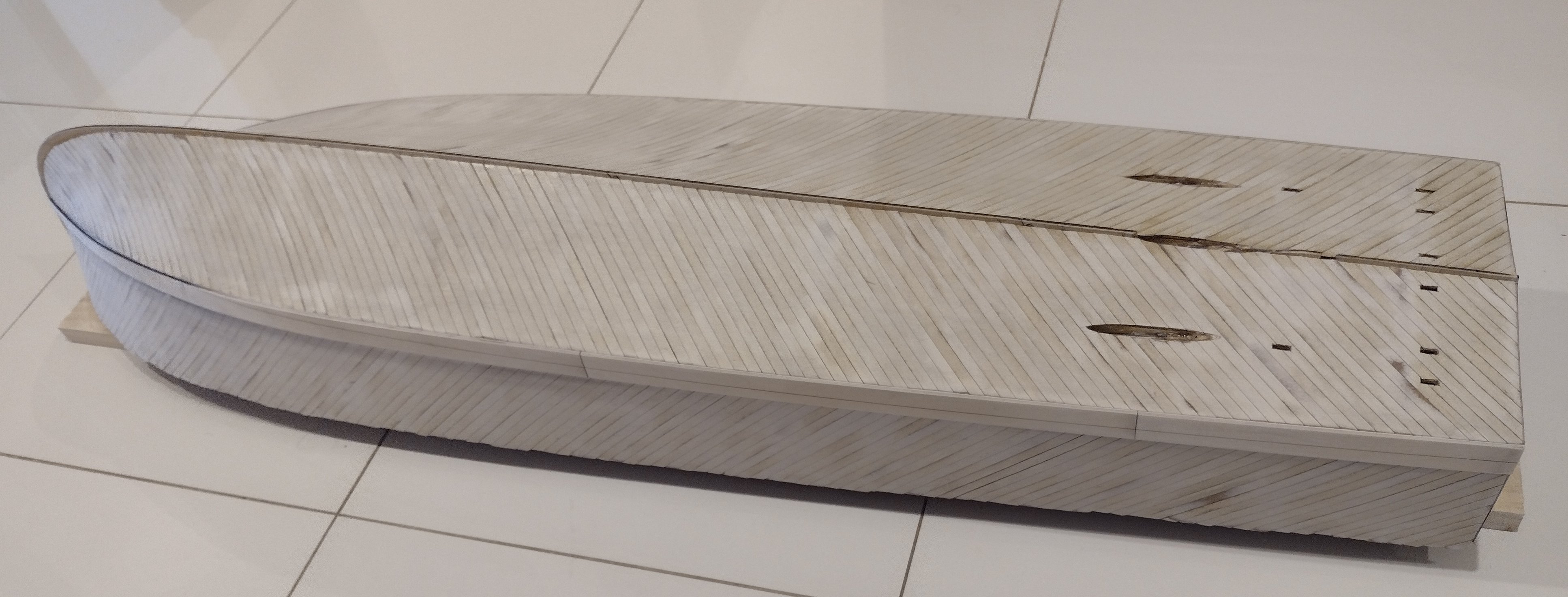
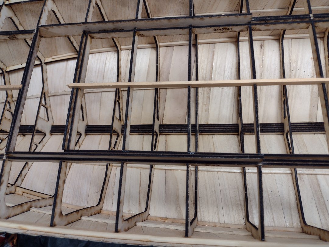
The sides planked with the first layer, a mixture of 1mm Balsa wood and some slightly harder wood called "Paulownia" cut into strips around 30mm wide.
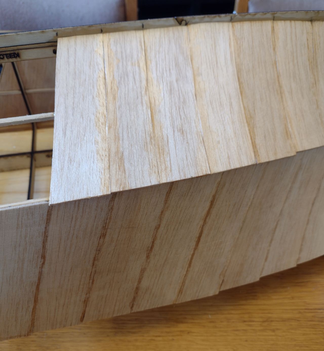
The bottom fwd section planked with the first layer.
The bottom aft section planked, again with Paulownia.
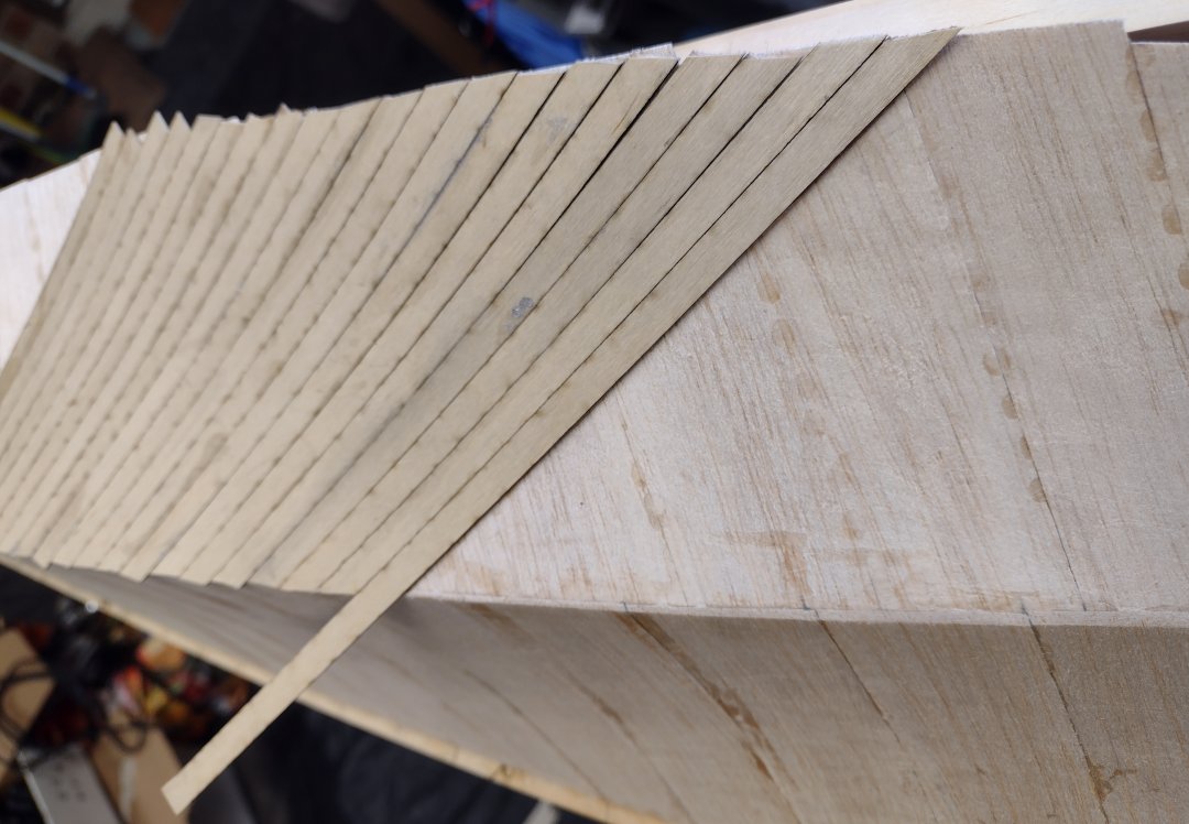
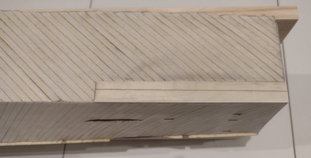
The beginning of the side second layer planked, with laser cut planking.
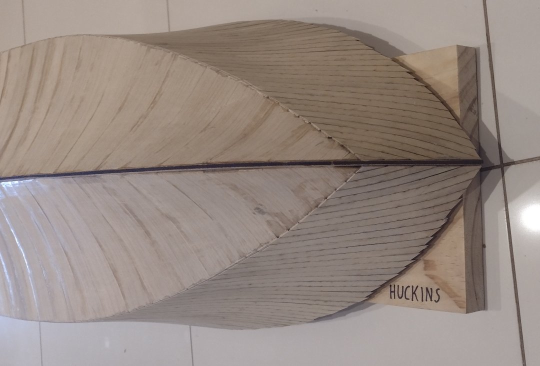
Both sides fully planked.
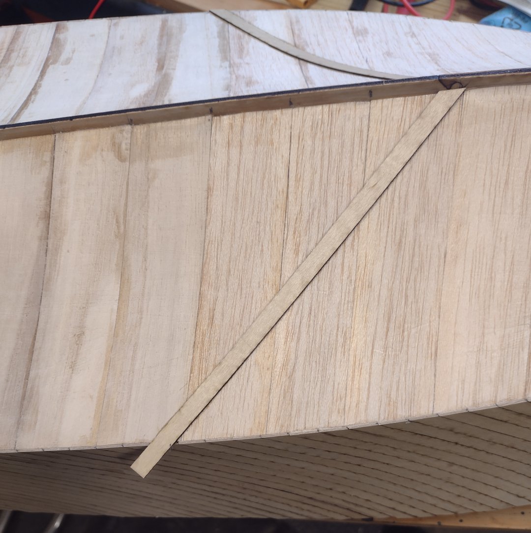
Get the first two laser cut planks correct on the bottom second layer.
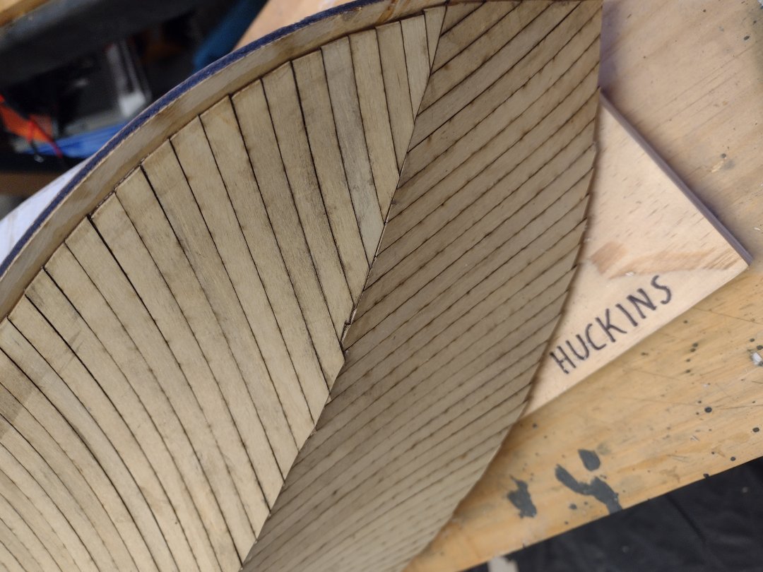
Bottom fwd planking with the transition from overlapping to butt joining.
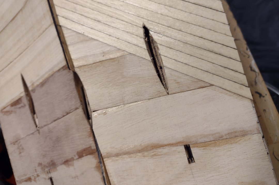
Cut planking neatly around the prop shaft holes.
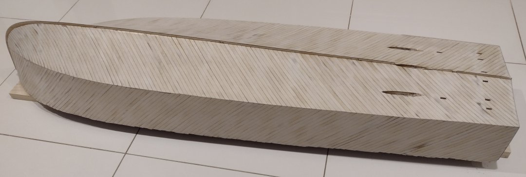
The second layer finished.
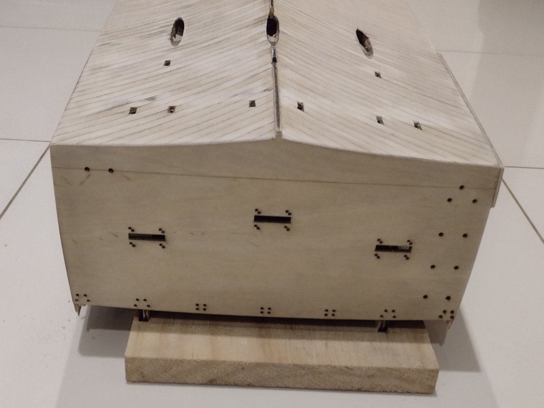
The belly band started on the port side.
The belly band aft started on the port side.
belly bands finished on both sides.
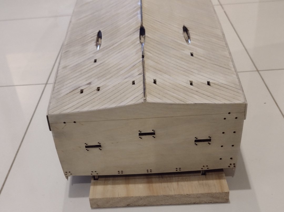
The belly bands finished from the stern.
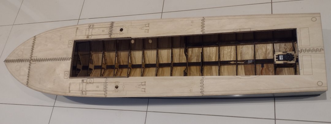
Remove the hull from the baseboard and trim up the deck runners.
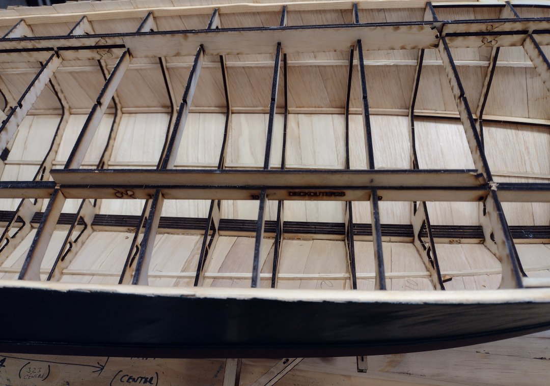
The deck runners all trimmed up and excess sections removed.
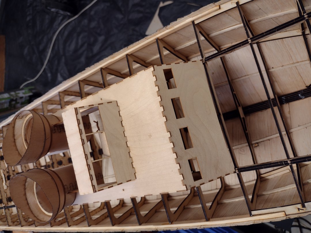
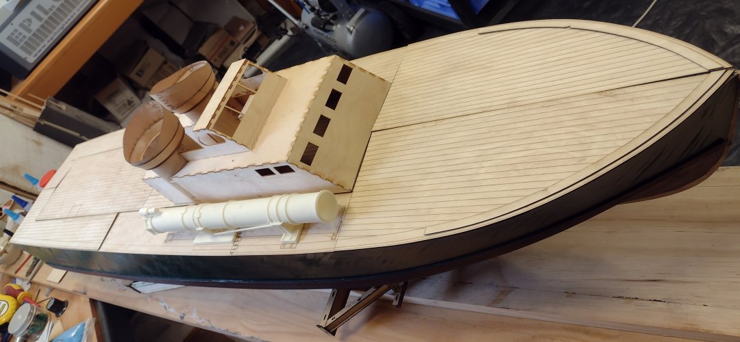
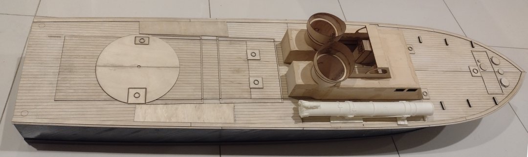
The test fit of the deck house, looks good!.
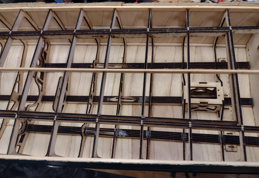
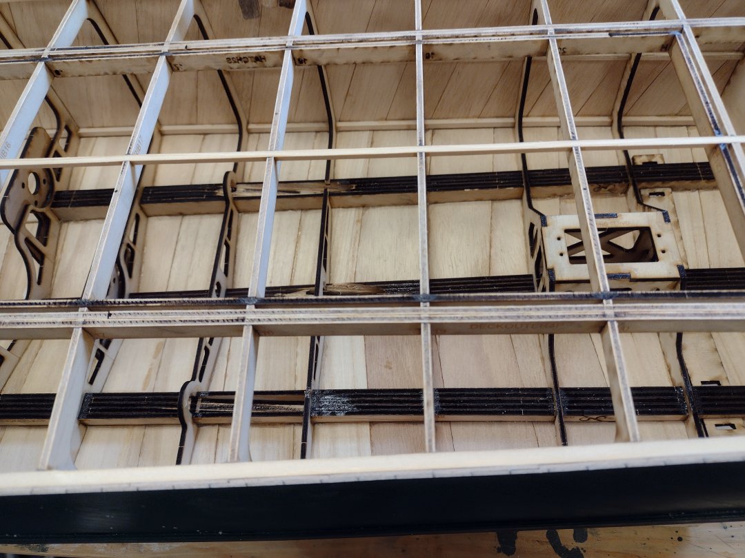
Install some deck stringers.
The deck stringer at the fwd end of the deck hatch.
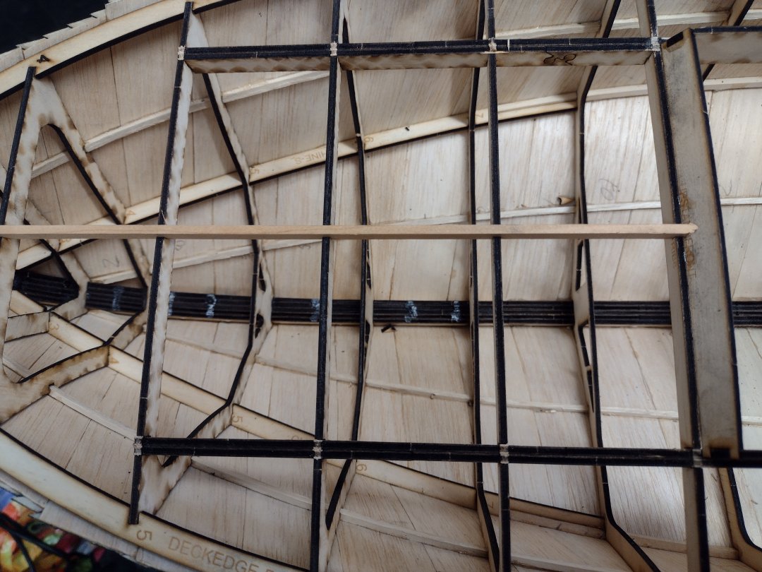
The deck stringer at the bow.
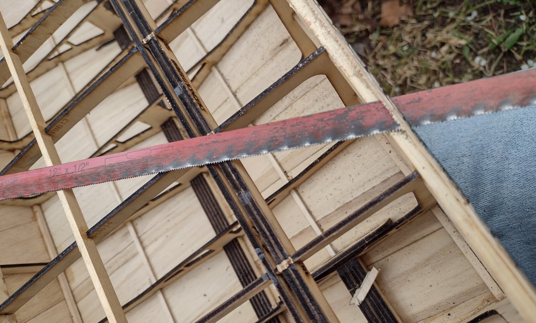
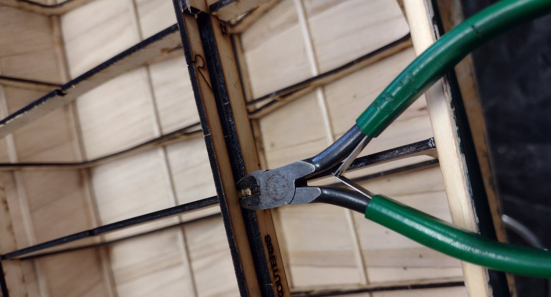
Cut away the excess side planking, with a hacksaw blade.
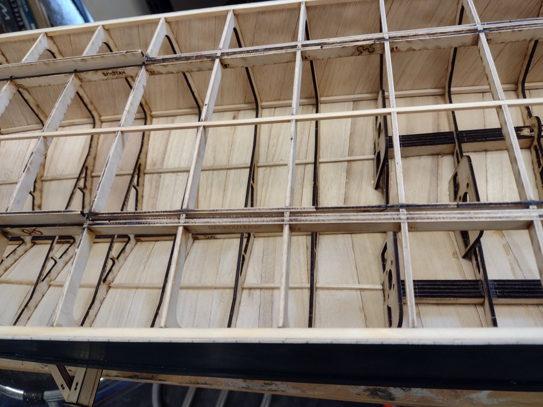
The deck runners, ribs and stringers all sanded down ready for the subdeck.
More deck sanding including the main hatch.
The rear subdeck hatch covering glued in place, doing it -in place- as part of the deck is the ONLY way to get it to fit properly.
Another view.
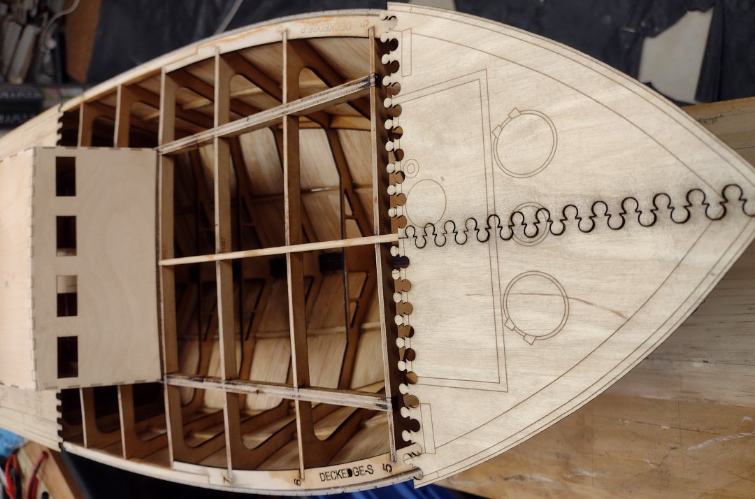
The trial of the subdeck pieces.
Trial fitting the aft subdeck.
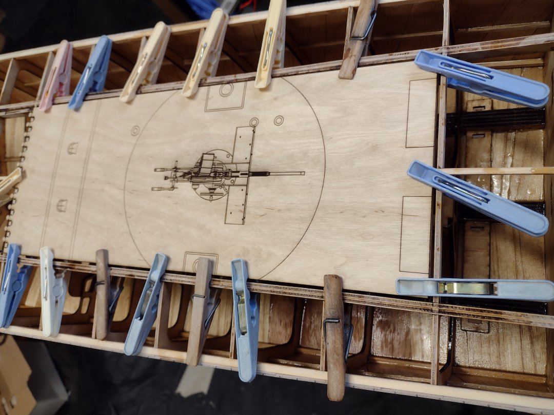
Trial fitting of the top deck pieces.
Once the hatch is fully covered, with the subdeck parts glued in place and fully dry you can cut around it and remove it.
Ta-Da, the hatch removed and the subdeck fully glued in place, I used Gorilla brand GEL superglue (cyanoacrylate) to do the deck fitting, as it takes a while to set.
The hatch with its top deck pieces glued on.
The top deck all glued in place, this is when you can tell if you built the hull -true-!
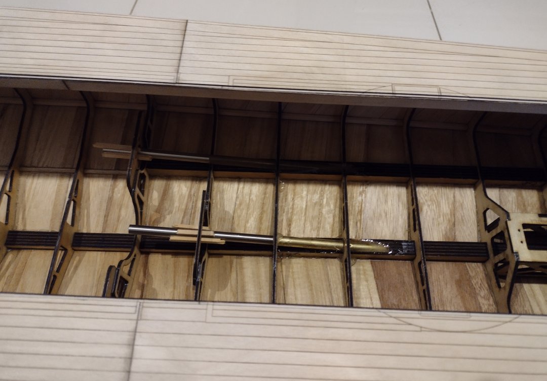
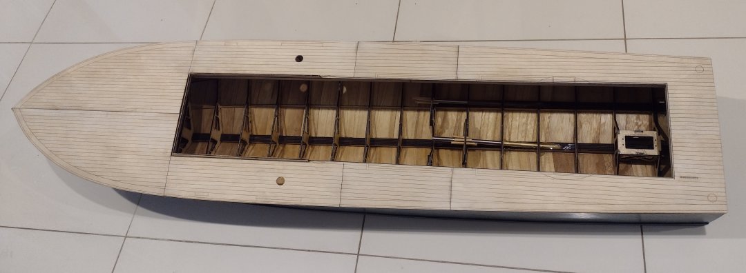
The propshafts installed, I used spare bits of 3mm square balsa to line up the inner shafts with the motor mounts. I used Araldite from the inside to fill all the voids.
The pretend hatch outlines and other bits glued in place.
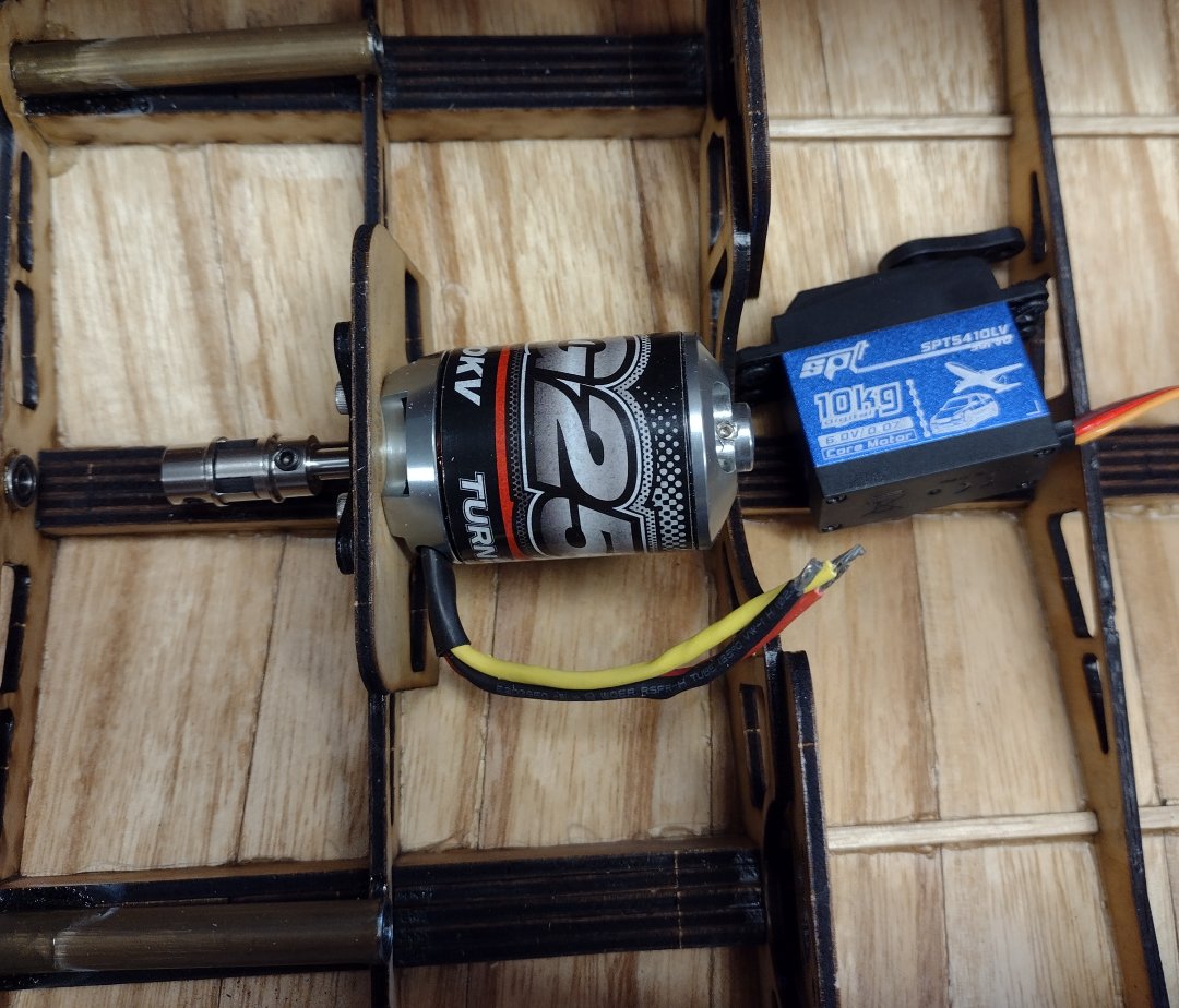
The first motor and universal installed.
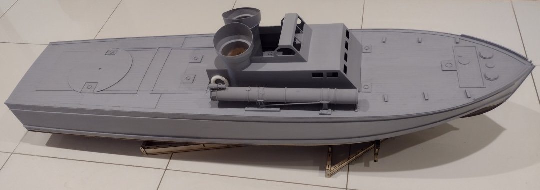
After sanding and painting, I chose Tamiya XF19 grey (after a few other hmmm colors).
I have also updated the rib designs for the laser cut kit to include an extra runner, between all the others, (so 4 more) to make it easier to plank.
My daughter had never seen one of my boats operating at the lake before so this day out was partially to show her how well they perform, she spotted a stick floating out in the lake and told me to stay away from it and I said "it's OK, it will eat the stick" just a second before a loud twang and the boat flipped over like an agile dolphin!
It seems that one of the (3) propeller shafts seized up at full speed and the inertia of the motor at speed (around 1500 Watts per motor) ripped the motor mount off the boat frame and flipped the boat upside down. It was quite spectacular and the boat floated upside down, without sinking, for nearly an hour until rescue could be undertaken. Very fortunately the boat remained intact and Malcolm managed to get the entire boat back for me! The motor stayed attached by it's connectors, the batteries stayed attached by their connectors as did the rest of the electronics, I must say I am amazed that it all survived!
Lillydale Radio Yacht Club Inc.I found a drone video of the Lillydale Lake sailing by "DroneHeart" https://www.youtube.com/watch?v=D22toKR9QNk which gives a great arial view of the fabulous lake we have.
I have repaired and strengthened the motor mounts in the Huckins so hopefully that doesn't happen again! I put an extra layer of 2mm Birch ply behind the 3mm thick motor mounts and also added a stiffener between the center and wing motor mounts to make them much more rigid. I have also run the motors at various speeds for long periods to free up and run-in the struts a little more so that hopefully they don't get hot and sieze up again! Interestingly I forgot to disconnect the batteries late on the 31st December and my son came banging on the bedroom door at 3am New Years morning, saying the boat was running - loudly, whoops, looks like the batteries in the transmitter went flat and the boat receiver went out of control. I have also reduced the steering aggressiveness a little bit by shortening the throw on the steering servo, I've actually ordered a new Hitec brand servo as the digital, strange brand, one I have in there is a bit jittery and I have built some new battery boxes to lay the batteries down lower and I have added 16 ounces or a little less than half a Kilo of lead weights in the base of the boat near the keel to make it more stable, added more weight in the bow section to stop it bouncing so much and lower it in the water a bit more. The Huckins is a very wide hull at the waterline so it tends to sit on top of the water, more so than the Elco or Higgins boats.