Electrics / The Brushed (Older) Motors Page
Electrics (Older - Brushed Motors)
See the Brushless motor page (2005) for Hull-2
(This is the Electrics and Motor detail from Hull 1 and is now getting fairly old but still relevant for some people.)
There is a fairly up to date article (Dec 2004) on the latest DC brushed electric motors for model boats on the RC Boat Modeler website that is worth having a look at, it's bit light on technical performance details though: https://web.archive.org/web/20070102194137/http://www.rcboatmodeler.com/pdf/MEGA_MOTOR_GUIDE.pdfR_GUIDE.pdf
The Electrics for this project will take a while to complete and there are several design aspects to it. We need to operate all the usual boat gear such as motor speed control, rudders etc but we also want to be able to independently launch each of the 4 torpedo's, sequence the launch of 16 rockets and hopefully fire the bigger guns, some of which may also need azimuth and elevation training control.
A further and more ambitious project is to have two way coms between the vessel and the captain's radio gear to enable live radar and/or camera feedback so that we can progress on to stealth warfare using feedback signals from the boats perspective - hide in the reeds and launch an attack on passers by!
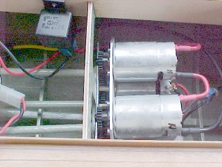
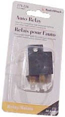
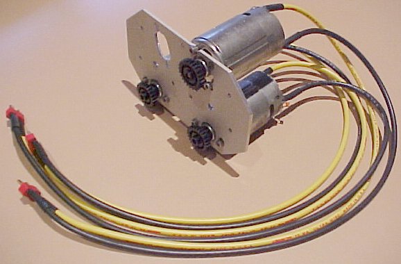
The initial performance of Hull-1 was a bit disappointing with two 480 motors fitted and a gear ratio of 2:1, so I built a new gearbox front plate that accommodated 4 Mabuchi style 550 motors and reduced the gear ratio's to 1.5:1, the bottom two motors were initially controlled by a "low Rate" electronic speed controller and gave me forward and reverse speeds and the top two motors were kicked in at high forward speed by a separate controller that I built some years ago that pulls in a 30A auto headlight relay (shown in the left picture below).
Later I developed a couple of different high rate DC brushed motor speed controllers.
I got Hull-1 "running on the step" at high speed with only the aft 1/3 in the water - most impressive! and there was much room for improvement in the type of propellers and probably gearing used. after 10 minutes of high speed running these motors were HOT!
With current's of around 30 amps continuous and much higher peak currents per motor pair (x2) and with huge battery capacity we have a very real risk of fire so it is extremely important that cables have sufficient cross sectional area and that all terminations are low resistance and are well soldered or crimped, they need to be kept well apart and well insulated with good quality (Polyolefin) heat shrink tubing. If you are not sure about the rating of your speed controller, don't use it! not all brushed motor controllers can handle the 14+ volts from these batteries when fully charged!
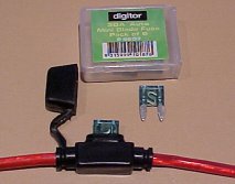
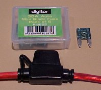
Here are some new 'mini blade' fuse holders and 30A fuses I found at the local 'Dick Smith' electronics shop, these are 'sort of' waterproof and have fairly flexible 12 Gauge wire, not as flexible as 'Deans' wire though. Any fuse will introduce some resistance!

I found these 'Super Deans plugs' and sockets that are used on high performance electric cars. They can be mounted back to back very easily if you need a power take off while maintaining a high current power feed through. There is no hole through the solder terminal so they need to be butt jointed to the cable with high quality soldering.
The 'top speed' controller development test bench
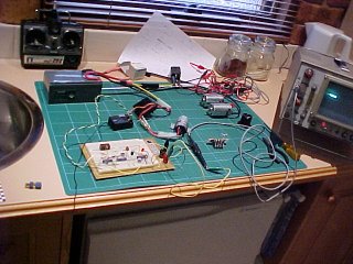
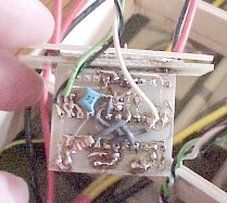
OK, I admit the implementation was a bit rough because I built it using some prototype PC cards that I developed some years ago when I tried designing a speed controller using an Altera programmable logic device, that was fairly hopeless. Some of the new power FET's now available have 'on-resistance' as low as 0.002 ohms and current ratings in the hundreds of amps range, so making an electronic version of the headlight relay is reasonably trivial, in fact this controller has 5 x BUZ11 FET's in it so it certainly has the current handling capacity to be used to directly control the 'overdrive' motor pair, but I need to make sure I don't cause major earth currents and therefore electronic damage and fire, so I just use it to operate the relay for the time being. (1999)
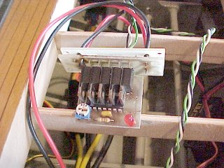
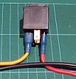
The 30A Headlight Relay
My existing speed controller died so I had to design a new one!
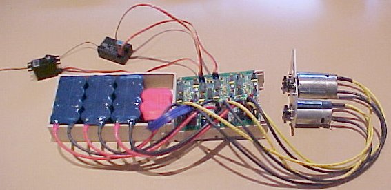
2004 - The latest electrics with the new triple speed controller
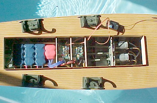
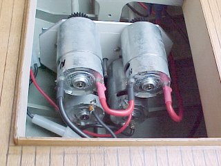
The brushed motor electrics mounted in Hull-1
The three motors mounted on gearbox plate no2. This caused a few problems because the plate was metal and all the motors have interference capacitors from each terminal to their body which are also metal. The triple speed controller worked fabulously on the bench but refused to behave in the boat. I could not solve the receiver interference issues until I twigged to what was happening and made a new front gearbox plate out of fibreglass pcb material with all the copper etched off, instant fix, I can now put the receiver and antenna wire in amongst the motor wiring and it behaves perfectly, even with the transmitter at a distance.
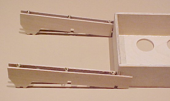
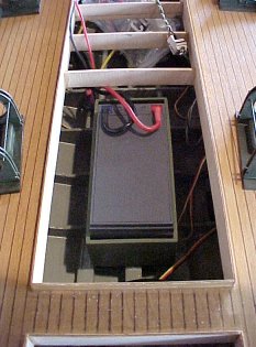
Hull-1 battery box and speed controller mounting rails
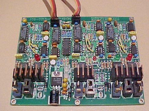
The triple brushed DC motor speed controller with battery eliminator (BEC) and rudder mixer
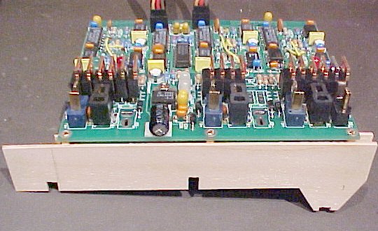
How the speed controller mounts on the rails
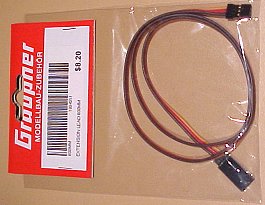
An extension lead for the rudder servo as it is "a long way to the back when you want to rock and roll"!
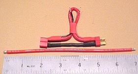
A simple current meter "shunt" - 7.55" of Dean's 12G Ultra or Wet Noodle wire will drop approximately 1 millivolt for every 1 Amp of motor current which you can read off on a good quality voltmeter or oscilloscope directly as current i.e Amps = milliVolts. The resistance spec for 12G copper wire at 20 deg C is 1.588 milliOhms per foot. There are two small wires soldered to the ends of the long wire to connect the meter to so the connector terminals can be covered with heatshrink. Keep the 12 G black wire as short as possible. Also bear in mind that the resistance of copper wire increases with temperature by about 1% for every 2.5 degrees C rise.
I split the Electrics into several pages so see these pages for the latest developments.
See also the new brushless Motor Page (2005) for Hull-2
Stay Tuned.