1/20th scale Operational Rocket Launcher
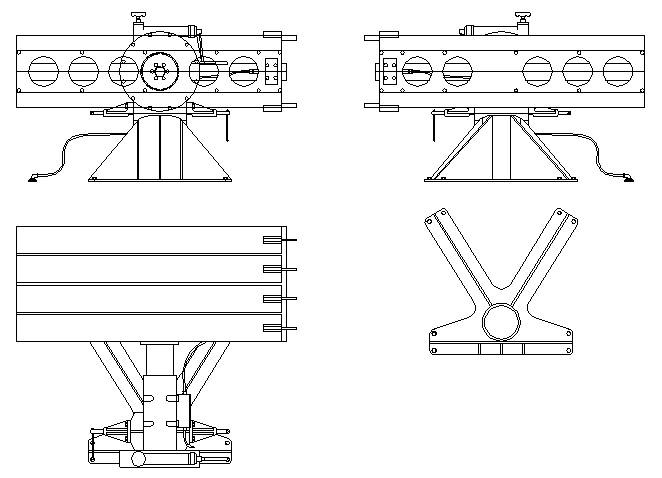
The objective is an operational 1/20th scale Rocket Launcher.
The plan is to use Micro Maxx rocket motors which are 1/20 scale 5" = 1/4", these are inexpensive, relatively safe, and come 8 to a pack - enough for one launcher.
Some test firings have been conducted from a 7mm (ID) (7.9mm OD) brass tube using the Micro Maxx supplied electric starters but with the plastic parts removed, this allows the starter to fit inside the tube and also inside of some stabilising fins mounted on the rear of the rocket motor. The tests were conducted with standard motors which contain a 1 second timer between the initial launch thrust and the main firing, these are unsatisfactory for anything other than strictly vertical flight as the motors fall to the ground (or water) during the delay, what we need are second stage motors with no delay.
Some experimentation with rocket stabilising fins is still required, the originals were spin stabilised, we may have to do the same.
 The assembled Launch head, I have left enough room between the top and bottom rows for some
sequencing electronics, this will contain some sort of timer and 8 power MOS
fets to sequence the electric starters
The assembled Launch head, I have left enough room between the top and bottom rows for some
sequencing electronics, this will contain some sort of timer and 8 power MOS
fets to sequence the electric starters
The base 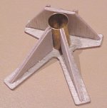
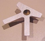
I'm not sure if this base is going to be strong enough as the launcher is getting reasonably heavy.
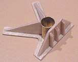
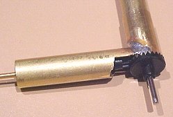 The basic elbow made
using AFX gears, this elbow contains elevation stops and operates the swing out
mechanism as well, I'm very pleased with the operation.
The basic elbow made
using AFX gears, this elbow contains elevation stops and operates the swing out
mechanism as well, I'm very pleased with the operation.
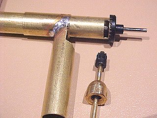 The basic internal
detail showing the crown and pinion AFX gears, the crown gear is a press fit on
the 7mm ID inner tube but will be glued in place fairly much as the last thing.
There is a hole through the outer horizontal tube in the centreline of the
vertical tube that the end of the pinion gear goes through and then the end of
the pinion gear fits into the slot in the inner horizontal tube to act as the
elevation stops.
The basic internal
detail showing the crown and pinion AFX gears, the crown gear is a press fit on
the 7mm ID inner tube but will be glued in place fairly much as the last thing.
There is a hole through the outer horizontal tube in the centreline of the
vertical tube that the end of the pinion gear goes through and then the end of
the pinion gear fits into the slot in the inner horizontal tube to act as the
elevation stops.
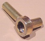 The basic knuckle
fitted to the elbow, this was made from a couple of brass washers and some thin
brass strip, soldered up seperately, drilled out to the correct sizes and then
carefully soldered onto the elbow
The basic knuckle
fitted to the elbow, this was made from a couple of brass washers and some thin
brass strip, soldered up seperately, drilled out to the correct sizes and then
carefully soldered onto the elbow
 The crown gear fits
snuggly through the outer knuckle assembly hole, in fact we may waste another
crown gear over the top of this one shown to form the visible elevation dial as
the exposed detail is very close to what we need and they are inexpensive.
The crown gear fits
snuggly through the outer knuckle assembly hole, in fact we may waste another
crown gear over the top of this one shown to form the visible elevation dial as
the exposed detail is very close to what we need and they are inexpensive.
 The side plate, I
regret not putting another 8mm hole in the inner side plate to fit the
horizontal inner tube into.
The side plate, I
regret not putting another 8mm hole in the inner side plate to fit the
horizontal inner tube into.
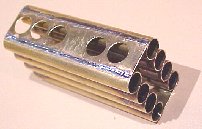
 The launch tubes
 The launch tubes
soldered in stacks of 4, only soldered from the inside, keep the outsides clean for painting..
The launch tubes
soldered in stacks of 4, only soldered from the inside, keep the outsides clean for painting..
Original 5" Rocket and Launcher Detail.
from:
NAVAL ORDNANCE AND GUNNERY
VOLUME 1, NAVAL ORDNANCE
CHAPTER 11
ROCKETS AND GUIDED MISSILES
B. Rockets Fired From Surface Craft
11B1.
General
As the previous article stated, the most important operational Navy rockets
fired from surface craft are the spin-stabilized 5.0-inch (of which there is an
entire family, with matching heads and motors), and two fin-stabilized A/S
rockets, one 7.2-inch and one 12.75-inch. The 4.5-inch barrage rocket is now
considered quite obsolete, and therefore is not taken up in this text.
The 7.2-inch and 12.75-inch rockets are designed to serve primarily as launching
devices for A/S charges (although the 7.2-inch type can be used against surface
targets when equipped with the proper type of fuze). They arc therefore
discussed elsewhere in this course, along with other A/S weapons. The remainder
of this section is devoted to the 5.0-inch spin-stabilized surface-fired rocket.
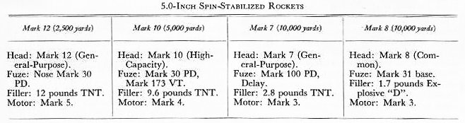
11B2.
5.0-inch spin-stabilized rockets
These rockets may be divided into three types, with respective maximum ranges of
2,500, 5,000, and 10,000 yards. All three have the same over-all length, so that
they may be fired interchangeably from the same launchers. The shorter-range
rockets, requiring smaller motors, are therefore provided with larger heads. For
example, the 2,500-yard rocket has a small motor, and a large head that contains
about 12 pounds of explosive. The 5,000-yard rocket is about half motor and half
head; it carries a 9.6-pound bursting charge. The head of the 10,000-yard rocket
contains only about 2.8 pounds of explosive.
The bursting charges, heads, fuzes, and motor designations of 5.0-inch
spin-stabilized rockets Marks 12, 10, 7, and 8 are compared in the table on page
250.
Rockets of this type are
designed for shipboard use, to which end several launchers or launcher
assemblies have been developed. Spin-stabilized rockets have proved very
effective for beach neutralization and shore bombardment when fired by LSMR or
other Inshore Fire Support type vessels. Their relative neutralization effect,
as compared to 5�/38 AA Common projectiles, is as follows: 1 Mark 12 (at 2,500
yards) equals 2 AA Common projectiles; 1 Mark 10 (at 5,000 yards) equals 1.7 AA
Common projectiles; I Mark 8 (at 10,000 yards) equals 1 AA Common projectile.
Since an LSMR-IFS vessel has a firing rate of 250-350 rounds per minute, these
rockets give these relatively small ships a fire power almost equal to that of a
light cruiser in weight of projectiles per minute. The general-purpose and
common rounds are particularly well adapted to PT-boat attacks at ranges up to
10,000 yards.
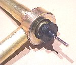
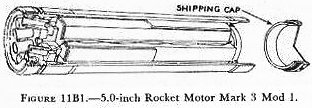
11B3.
5.0-inch rocket motor
The 5.0-inch Rocket Motor Mark 3 is used to propel common and general-purpose
5.0-inch spin-stabilized rockets. It is shown in figure
11B1. The motor tube is about 22
inches long. It houses the propellant and serves as a combustion chamber. The
motor tube has internal threads and an external bourrelet ring at each end. A
shipping cap is screwed into the front end of the motor tube during shipment.
The front closure is a sheet-metal disc pressed in position near the front end
of the motor tube. This front closure seals the forward end of the motor tube
and holds the igniter and propellant in place. There is a light, metal blow-out
disc in the center of the front closure; on its inner surface a thin felt pad is
cemented. Just inboard of this pad is the igniter, which is a flat, tinned case
containing 35 grams of black powder and an electric squib. Two wires pass from
the squib to the rear of the motor tube, where one wire is connected with the
contact ring and the other wire is grounded to the motor tube at the nozzle-ring
plate. A 1-inch thick felt washer is placed forward of the propellent grain to
protect against accidental shock.
The propellent used in this motor is an inhibited, cruciform extruded grain of
Ballistite weighing about 10 pounds. A plastic inhibitor is cemented to both
ends of the grain, and plastic inhibitor strips are cemented on the webs. These
inhibitors control the burning area of the grain and thus regulate the pressure
developed within the combustion chamber during the burning period. The
nozzle-plate assembly consists of eight nozzles and a grid mounted on a nozzle
plate. The nozzles have a 12-degree cant, which produces clockwise rotation when
the rocket is fired. At the after end of the motor is an assembly consisting of
a nozzle-plate ring and an insulated contact ring. The nozzle-plate ring has
external threads which engage internal threads of the motor tube. The contact
ring is riveted to the nozzle-plate ring, but electrically insulated from the
latter. The nozzle-plate ring and the contact ring act as terminals of the
igniter electrical circuit. A short-circuiting band creates a short circuit
between the nozzle-plate ring and the contact ring; it is removed when the
rocket is prepared for firing. The after end of the motor tube is sealed by a
thin metal disc cemented in place within the rear of the nozzle-plate ring.
Front and rear closures of the motor tube should remain in place at all times;
if a closure has been broken, the motor should be turned over to an ammunition
depot or disposed of by lowering into deep water.
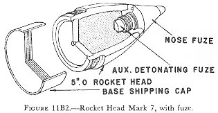
11B4.
5.0-inch spin-stabilized Rocket Head Mark 7 and fuzes
Rocket Head Mark 7 and Mods is used for general-purpose rounds in the case of
the 5.0-inch spin-stabilized rockets. This head, with nose fuze in place, is
shown in figure 11B2.
When shipped, the head is protected by a nose shipping plug and a base shipping
cap. The head is closed at the after end, where it is threaded externally for
assembly to the Motor Mark 3. The forward end of the rocket head is internally
threaded to receive the adapter, on which the Auxiliary Detonating Fuze Mark 44
Mod 2 is mounted. When the adapter is screwed into the forward end of the body,
the auxiliary fuze is properly positioned within the body. The Nose Fuze Mark
100 Mod 2 is then screwed into the adapter. The rocket head contains a 2.8-pound
charge of TNT.
The Nose Fuze Mark 100 is a selective-action type which is armed by rotation
during flight. A selector in the side of the fuze body may be turned to DELAY or
S. Q. (superquick). The amount of delay incorporated is 0.025 second.
11B5.
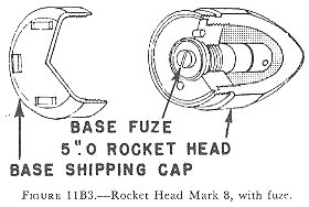
5.0-inch spin-stabilized Rocket Head Mark 8 and fuze
The Rocket Head Mark 8 and Mods is also used for assembly with the Mark 3 motor.
The Mark 8 head, designated for common rounds, is a hollow steel shell with a
solid nose, containing a 1.7-pound charge of Explosive D. It is shown in figure
11B3. Its after end bears external
threads for assembly to the motor; it also is threaded internally to receive an
adapter. The Base Fuze Mark 31 is screwed into this adapter. The head is shipped
with the base fuze in place, and protected by a base shipping cap. The latter is
removed when the head is assembled to the motor. Personnel must not attempt to
remove the base fuze from the head at any time. This fuze is armed by rotation
during flight, and functions upon impact.
11B6.
Stowing and assembly of 5.0-inch spin-stabilized rockets
The motors of 5.0-inch spin-stabilized rockets should be stowed in the shipping
boxes or tanks in which issued, in smokeless-powder magazines where temperatures
are maintained below 90 degree F. Prolonged stowage at or about 100 degree F. is
considered to be hazardous. Where magazine stowage in shipping boxes is not
practicable, the Bureau of Ordnance prescribes special stowage conditions.
Motors should not be stowed in the same compartment with or near electronic
apparatus or antenna leads.
At the discretion of the Commanding Officer, ready-service rounds may be stowed
with the rounds pointing outboard if practicable. Fuzing of general-purpose and
high-capacity rounds should be delayed as much as is commensurate with the
tactical situation. The rockets should be kept in the shade, and should not be
fired if motors have been exposed for more than an hour to temperatures outside
the safe temperature limits specified on the motor tubes.
In assembling the rocket, the gasket and shipping cap are first removed from the
motor tube. Forward and after closures of the motor tube must remain in
position. The base shipping cap is now removed from the head. A Mark 8 head must
be examined to assure that the base fuze is in place; if not, the rocket head
must be disposed of. If such a rocket head were assembled to a motor, the main
charge would detonate when the motor was fired. Strap wrenches and bench clamps
are now used to engage the threads of the motor and head until the seating
surfaces meet firmly. In the case of the Mark 7 rocket head, a further step is
to remove the nose plug and make sure that the auxiliary detonating fuze is
present and screwed in the nose fuze.
In disassembling 5.0-inch spin-stabilized rockets which have Mark 7 heads, the
nose fuze is first removed and replaced by the nose plug. It is necessary to be
sure at this stage that the short-circuiting band remains on the motor, or has
been replaced thereon. Strap wrenches and bench clamps are then employed to
disengage the motor and rocket head. The base shipping, cap is replaced on the
head, and the gasket and shipping cap are replaced on the motor. The bourrelet
rings are greased lightly to prevent rusting, and the rocket head and motor
replaced in the shipping box. In disassembling 5.0-inch spin-stabilized rockets
which have Mark 7 heads, the nose fuze is first removed and replaced by the nose
plug. It is necessary to be sure at this stage that the short-circuiting band
remains on the motor, or has been replaced thereon. Strap wrenches and bench
clamps are then employed to disengage the motor and rocket head. The base
shipping, cap is replaced on the head, and the gasket and shipping cap are
replaced on the motor. The bourrelet rings are greased lightly to prevent
rusting, and the rocket head and motor replaced in the shipping box.
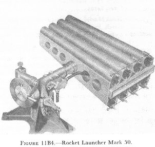
11B7.
5.0-inch Rocket Launcher Mark 50
One of the launchers used to fire 5.0-inch spin-stabilized rockets is the Mark
50, shown in figure 11B4.
This is an 8-tube launcher designed for use on PT boats. Two launchers are
mounted on each boat; they may be swung inboard for loading and outboard for
firing. The barrels are arranged in 2 rows of 4 each, 1 row above and the other
below a horizontal supporting shaft. Elevation is adjustable, and train is
effected by turning the PT boat. When a firing button is depressed (on the
bridge), one rocket is fired from each launcher. Current to fire a motor is fed
to a rocket by means of the contact ring. The electrical impulse passes from the
contact ring to the squib, causing the latter to set off the black powder in the
igniter.
A. Rockets
and the Rocket Principle
11A1. Definitions
A rocket is a missile propelled by the escape of gases produced from the burning
of solid, liquid, or gaseous propellants completely contained within itself. A
true rocket by definition does not, for example, use atmospheric oxygen to burn
its fuel.
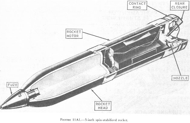
Figure 11Al
shows the external appearance of one type of rocket. The head of this rocket
contains a high-explosive charge and a nose fuze to initiate detonation. The
motor contains the combustion chamber, and houses the propellant charge. Hot
gases from the combustion chamber issue from a nozzle at the after end of the
assembly.
Rockets exhibit two characteristics unique in the field of propulsion: (1) the
propulsive force delivered is independent of atmospheric air, and thus the
rocket may be propelled through empty space, and (2) the propulsive force is
unaffected by the velocity. One of the challenging problems in rocket design is
to develop an acceptable degree of stabilization in flight. The rocket shown in figure
11A1 represents a spinstabilized
rocket.
11A2.
History of rockets
Rockets were used in the Far East as early as the 13th century. In the first
decades of the 19th century several western armies employed rocket projectiles
with greater or lesser success, a notable incident in the history of our own
country being the use of rockets by the British during the attack on Washington
in the War of 1812.
But the military use of rockets languished after the middle of the 19th century,
attention being diverted from them by improvement in guns and gunnery.
Projectiles fired from guns proved to be superior to rockets in both range and
accuracy. So for many years the employment of rockets was largely associated
with pyrotechnic displays. During World War II, however, the development of
military rockets under-went a considerable revival in the United States, Great
Britain, Germany, and the U.S.S.R. Short-range rockets were developed for use
against shore installations, ships, tanks, airplanes, and personnel. The Germans
produced a long-range rocket missile known as the V-2.
11A3.
Principles of rockets
A rocket motor is a metal tube that serves as a combustion chamber. The burning
propellant generates hot gas, and the gas pressure within the combustion chamber
rises quickly to some value determined by the amount and characteristics of the
propellant and the size of the nozzle or nozzles. The gas exerts approximately
the same outward pressure on each square inch of surface within the combustion
chamber; however, the gas rushes out of the nozzle without exerting any force
upon the area of the opening, but with exertion of full force upon the
corresponding area at the forward end of the combustion chamber. Thus a net
force or thrust acts in the forward direction. The magnitude of this force is
roughly the area of the orifice in square inches multiplied by the internal
pressure in pounds per square inch.
Fundamental to rocket propulsion, then, is the conversion of heat energy into
kinetic energy by an adiabatic expansion. This poses two basic problems: (1) to
generate gas under high pressure and at a constant rate-a problem of chemical
reaction; and (2) to direct the high-pressure gases into a high-velocity
stream-a problem of nozzle design. Pressure in a rocket motor depends largely
upon the burning rate and escape rate. In the case of solid-fuel rockets, for
example, the composition of powder, shape of grain, and rate of burning, which
have important relationships to performance as discussed in chapters
2 and chapters
3, are also important factors in
rocket design.
a. Rocket motors. The thrust of a rocket motor is an equal and opposite reaction
to the expansion of gases discharged at the nozzle; and since the expansion of
these gases is maximum in a vacuum, rockets function most efficiently in such a
medium. Rocket motors contain all the essentials for functioning, and do not
require atmospheric oxygen for combustion.
Consider the nozzle in a little
more detail.
The function of the nozzle is to permit the hot gas produced by the burning
ballistite propellant to flow out of the rocket motor, pushing the rocket along
as it goes.
The shape of the nozzle determines the characteristics of gas flow, and hence
has much to do with how efficiently the gas flow propels the rocket. Gas flow
must be smooth (nonturbulent). For a smooth, controlled trajectory, it must
produce thrust along the long axis of the rocket. And the nozzle must be
designed to develop every possible bit of thrust from the flow.
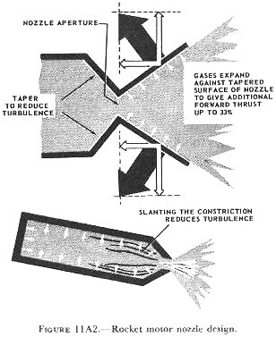
By tapering the rear of the chamber so that it narrows smoothly toward the
nozzle aperture, a smooth, nonturbulent flow of escaping gas is created. This
tapered section forms the forward half of the nozzle. The tapered extension,
forming the after end of the nozzle, which leads outward from the nozzle
aperture, forces the escaping gas, as it expands to furnish additional (about 33
percent) forward thrust. (Fig. 11A2.)
Many rockets have a number of nozzles, rather than just one. The same principles
apply there.
The rocket MOTOR TUBE contains the propellant charge and igniter. It is a
combustion chamber in which the propellant is burned to provide the motive power
(hot gases) for the rocket. It generally threads to the rocket or an adapter in
the base of the head, and is usually shipped separate from the head. The
diameter of the motor is less than that of the head in some rockets; in others
its diameter is about the same as the head�s.
The IGNITER contains black
powder loosely packed, and an electric SQUIB with a low-resistance bridge wire
running through a match composition.
All present types of rocket motors are initiated electrically. As figure
11A3 shows, the firing impulses may be
transmitted either (in aircraft rockets) by a pigtail lead from the rocket
plugged into a source of firing current, or (in surface-launched rockets) by
contact surface on the shroud surrounding the rocket�s tail.
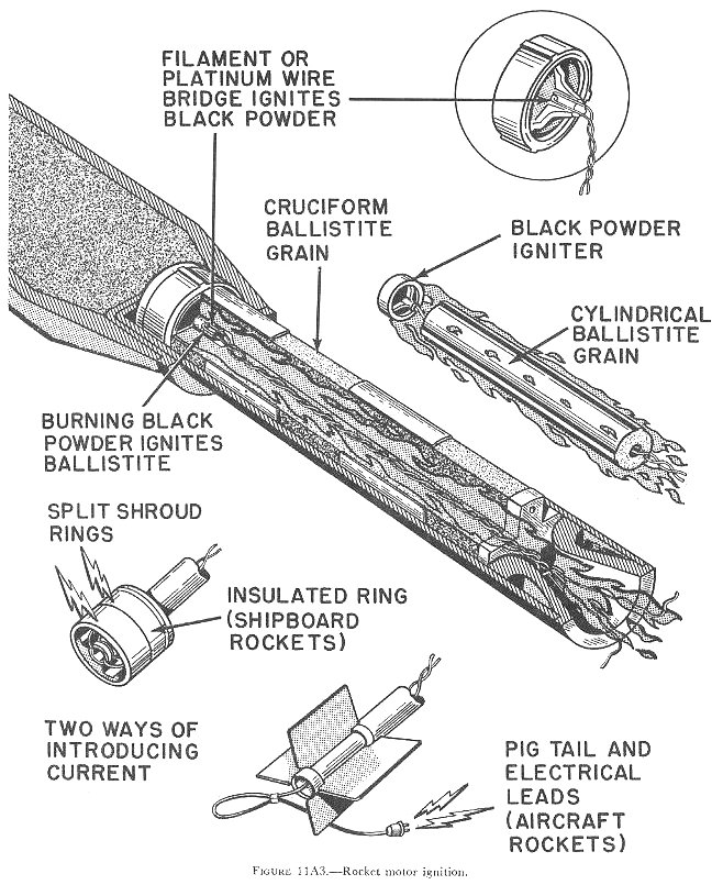
Most Navy rockets use either (fig. 11A4) a solid cruciform grain or a cylindrical grain with an axial hole and radial perforations. The latter, often used in Navy ground or shipboard mounted rockets, is characterized by three ridges spaced 120 degrees apart and running longitudinally along the grain. The cruciform grain, usually found in Navy aircraft rockets, in section is a symmetrical cross. If all of the exterior surface of this grain were permitted to burn, there would be a gradual decrease of area, and the burning rate would be regressive----that is, the rate of gas production would decrease as the grain continued to burn. Since a uniform burning rate is desired, a number of slower burning plastic strips or INHIBITORS are bonded to certain parts of the area exposed on the outer curved ends of the arms. These slow the initial burning rate, and gas production rate is approximately uniform as long as the grain burns.
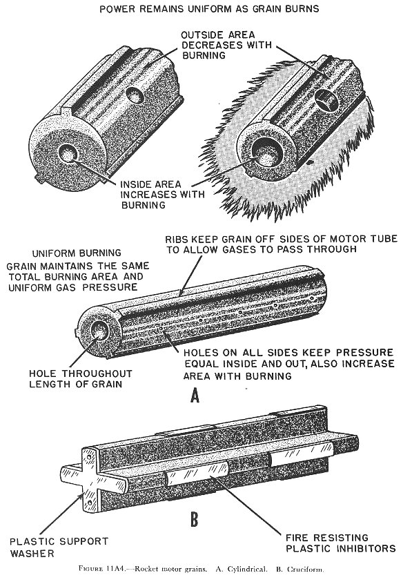
Hollow cylindrical grains have inherently uniform burning rates and usually
require no inhibitors.
Grain sizes vary according to the motor in which they are to be used. Most use
only a single grain, but some may use up to four.
The grid is a metal piece near the nozzle which supports the propellent grain so
that sufficient clearance is allowed between the grain and the nozzle to permit
a free flow of gas through the nozzle. Without the grid, the grain will move
aft, blocking the nozzle and causing excessive pressures to build up in the
motor.
Tail fins provide stability in flight, prevent tumbling, and ensure head-on
impact. During burning, the action of the air against the fins tends to resist
side forces of the nozzle and to improve the accuracy of fire. When there is a
tail shroud around the fins, it supports the rear end of the rocket in the
launcher.
Most newer shipboard-fired rockets are SPIN-STABILIZED; that is, their nozzles
are canted to exert torque as well as forward thrust. The result is that the
rocket spins like a gun projectile in flight. Such rockets, of course, have no
fins. Since spin begins as soon as the propellant starts to burn, the
stabilizing effect begins as soon as sufficient thrust is developed to launch
the rocket.
Aircraft rockets are fin-stabilized designs. (To save space, folding fins that
open on launching are often used.) Fin stabilization is poor when a rocket is
launched at zero or low air speed (as is the case on surface craft); in
aircraft, however, the plane�s air speed ensures good stabilization at the
instant of launching.
Rockets have been designed with canted fins, to produce spin. This kind of
design is, however, subject to the drawbacks common to other finned rockets.
b. Rocket heads. As previously noted, the head of a conventional rocket contains
a high-explosive charge capable of being detonated by action of a fuze or fuzes.
Use of centrifugal force and setback to arm fuzes, as in gun projectiles, is not
universally applicable to rocket fuzes. In part, this is because rockets
accelerate at a lower rate than do gun projectiles; moreover, with
fin-stabilized rockets no centrifugal forces are available. For these reasons
various other devices are employed to arm rocket fuzes. The fuzes of some
antisubmarine rockets, for example, are armed either by hydrostatic pressure or
by rotation of a propeller after travel of 15 to 20 feet in the water. When
armed, such rockets detonate upon impact with any solid object. Several methods
have been utilized to arm the fuzes of barrage or bombardment rockets so that
they will detonate upon impact or after a predetermined delay. In one type of
nose fuze, arming depends upon rotation imparted to a small propeller as the
rocket moves through the air. A base-detonating type is armed by a mechanism
that is actuated by pressure in the rocket motor during burning.
On the other hand, fuzes used on spin-stabilized rockets may be similar to the
fuzes of gun projectiles, since centrifugal force is present.
c. Rocket launchers. Modern rockets are launched from various types of
launchers, which in essence are mechanisms designed to point the rocket in the
right direction and to actuate or ignite the motor. One significant fact about
launching is that there is little or no recoil. The forward momentum given to
the rocket is balanced by the rearward escape of propellant gases. Therefore, a
very large total weight of �pay load� may be fired from boats, airplanes, or
other conveyances which could not possibly withstand the recoil shock incident
to firing equivalent projectiles from traditional types of larger guns. This is
why the development of aircraft rockets, to cite one example, has been so
significant. Inability of aircraft structure to stand up under the recoil shock
of conventional-type guns had long been a limiting factor in aircraft armament.
Until the rebirth of military rockets occurred, the largest projectile fired by
most aircraft guns weighed only 2 or 3 pounds. The modern rocket-firing plane,
however, is capable of launching rockets which weigh over 1,000 pounds.
It also is noteworthy that many rocket launchers are relatively light in weight,
simple, inexpensive, and more readily replaceable than comparable guns. On the
other hand, much more propellant is required to bring a rocket up to a given
velocity than is the case with a gun projectile. Moreover, rocket fire (with
conventional short-range rockets) launched from the ground or from the deck of a
ship compares unfavorably in accuracy with gunfire.
Shipboard rocket launching devices always have a tube or rail which supports the
rocket until firing, and guides it during the critical initial portion of its
trajectory. This is necessary because, especially with fin-stabilized rockets,
the stability of the rocket is relatively poor until it attains a fairly high
air speed.
On fixed-wing aircraft, as has already been explained, fin stabilization of
rockets is effective at the instant of launching because of the plane�s air
speed. Rocket launchers in aircraft are therefore merely supports which hold the
rocket until launching, and then release it as the propellant is ignited. These
are called �zero length� launchers.
Shipboard launchers may be of �repeater� design to fire rockets successively
at short intervals from a magazine or loading device. Electrical contact to the
rocket�s squib in such launchers is made through a set of contactors which rub
against insulated metal contacts on the rocket. In aircraft launchers, only one
rocket is fired per launcher per flight. The electrical connection from plane
firing system to rocket is made through pigtail leads and plugs, which part upon
firing.
11A4. Rocket
trajectory and stabilization
Mention has been made of the fact that conventional rockets are less accurate
than gun projectiles. One reason for this is that gun projectiles are guided by
the gun bore during the entire period in which the propellant is burning and
maximum velocity is being attained. A rocket, on the other hand, is guided by
its launcher, if at all, during only a very small portion of the time that its
propellant burns; in all cases, maximum velocity of the rocket is attained after
it has left the launcher, and in some cases after the rocket has passed through
hundreds of feet of free flight. In addition, the center of gravity of a gun
projectile remains fixed in position in relation to the projectile while the
latter is in flight, whereas the center of gravity of the rocket necessarily
shifts in relation to the rocket as the fuel in the motor is consumed.
After a rocket has attained maximum velocity, it may traverse a trajectory
similar to the path traversed by a gun projectile. On the other hand, it is
possible to place lifting surfaces (wings) on the rocket head, which will cause
the missile to follow a glide path rather than a purely ballistic path, once
acceleration is completed.
The older type of rockets which came into widespread use during World War II
were fin stabilized. Such rockets have the advantage of being relatively simple
to manufacture, but are likely to prove somewhat cumbersome in handling,
launching, and stowing. It may be pointed out, however, that fin stabilization
is the type associated with a glide path of flight, and that stabilizing fins,
with proper adaptation, may be used as rudders and elevators in controlling the
path of flight. These facts take on special significance when we consider the
potentialities of guided missile.
Spin stabilization has also been used extensively in the case of rockets. A
spin-stabilized rocket, like a gun projectile, tends to maintain a relatively
stable course because of the gyroscopic effect resulting from its rotating
motion, which in part counteracts forces that otherwise would produce deviation
in line of flight. As a case in point, one type of 5.0-inch spin-stabilized
rocket developed during World War II had a nearly flat trajectory at short
ranges, and rotated at about the same or even higher speed than 5�/38 caliber
projectile.
In a gun projectile, rotary motion or �spin� is imparted by rifling of the
gun barrel. Spin-stabilized rockets, however, achieve a spinning motion because
they have several nozzles, slightly canted in position. Since fins are absent,
such rockets can be relatively compact, which makes for greater convenience in
handling, launching, and stowing. The degree of stabilization may also be
considerably greater than that of fin-stabilized rockets. The old fin-stabilized
4.5-inch barrage rockets, for example, had a dispersion of from 20 to 40 mils,
whereas the comparable figure for spin-stabilized rockets is about 20 mils. When
fired forward from airplanes, fin-stabilized rockets achieve a much better
performance.
Fired from aircraft, dispersion of fin-stabilized rockets may be no more than 6
to 8 mils. Comparable dispersion of gun projectiles would be a single mil or
less.
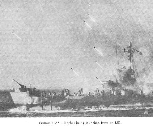
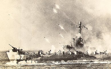
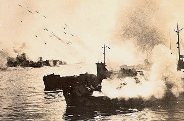
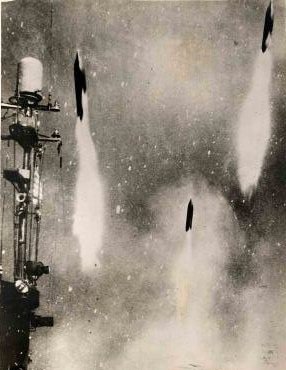
It therefore is evident that the accuracy of conventional-type rocket fire is not on a par with the accuracy of gunfire. Rockets, however, have proved to be extremely valuable weapons for special purposes. Examples include the employment of rockets in antisubmarine attacks, and the saturation of enemy-held beach positions by rocket fire launched both from airplanes and from the decks of landing ships. Figure 11A5 shows barrage rockets being launched from an LSI which is moving in toward a beach.
11A5. Rocket Fuels
From the standpoint of fuels there are two general types of rockets: those
incorporating liquid-fuel units as typified by the German V-2, and those
incorporating solid-fuel units as represented by various barrage rockets.
In liquid-fuel rockets, the fuel and the oxidizer are carried in separate
containers from which they are ejected into a relatively small combustion
chamber where the propelling reaction takes place. A comparatively elaborate
mechanism was used in the V-2 rocket to control this use of fuel and oxidizer;
however, simple designs have been developed subsequently which permit the use of
liquid propellants in high-performance antiaircraft rockets, less than 4-inch
diameter, capable of developing high thrust for a short period of time. Also the
fuel tanks of liquid-fuel rockets for guided missile propulsion can be so
located that change in center of gravity is reduced to a minimum as fuel
consumption proceeds.
Among the advantages of solid-fuel rockets is simplicity of design and
operation. A single chamber serves as a container for the propellant and as a
combustion chamber. Rate of gas production is controlled by the chemical
composition of the propellant (especially by the ratio of the oxidizing agent to
the fuel), by the operating pressure and temperature, and by the shape of the
propellent charge and combustion chamber. In some cases inhibitors, consisting
of slow-burning material attached to certain surfaces of the powder grain to
delay combustion, are used. A disadvantage of solid-fuel rockets is the
relatively great weight of the motor housing.
11A6. Naval uses of solid-fuel rockets
Rockets (but not guided missiles) fired by naval ships and aircraft are
designated by head diameter in inches. (This is analogous to the caliber of gun
projectiles.) The motor may be the same size as, or smaller than, the head, but
never larger.
Several types of rocket of 3-inch and smaller caliber are used for practice
firing, for targets at which other weapons can fire, or for signaling.
Subcaliber rockets which fit into the launchers of larger types and are used as
inexpensive substitutes for training purposes are also in this range of sizes.
Aircraft rockets intended for use against enemy targets or for other combat use
are made in 3.5-inch, 5.0-inch, and 11.75-inch sizes. (Other sizes may be under
development.) Rockets fired from surface craft arc the obsolescent 4.5-inch
fin-stabilized barrage rocket, several types of 5.0-inch spin-stabilized
rockets, a 7.2-inch rocket designed for antisubmarine use, and the antisubmarine
12.75-inch rocket.
11A7. General safety precautions in handling and firing rockets
1. Review of ordnance instructions. Frequent review of ordnance pamphlets and
the latest ordnance instructions pertaining to each piece of equipment should be
made mandatory by all authorities in command of units afloat and ashore,
wherever rockets are stowed, assembled, or fired.
2. Nozzle blast. It should be remembered that nozzle blast from a rocket motor
is intensely hot. Small pieces of burning powder frequently arc blown out of the
nozzles and may be hard to extinguish. Steel sheathing is therefore used to
protect decks and superstructure areas around launchers. Some launchers have
blast deflectors for protection of the immediate area, while others are mounted
slightly outboard, so that blast is directed into the water. It is obviously
unsafe for any one to be directly in front of or behind a loaded launcher, or
one that is being loaded. Personnel loading a launcher should always stand to
one side of the path that would he taken by rocket or blast in the event of
accidental or intentional firing. All personnel in the vicinity of a launcher
should wear long trousers, and long shirt sleeves buttoned about the wrists.
3. Firing precautions. The firing circuit must be open at all times until the
launcher is ready to fire. All extra rockets must be kept at a safe distance
from loaded deck-mounted launchers. No personnel may approach a loaded launcher
until the safety plug or firing key has been removed from the firing circuit.
The fuze safety wire must he reinserted as soon as the safety plug or firing key
has been removed, but not before. No test of the firing circuit may be conducted
until all rockets have been removed from the launcher and placed at a safe
distance. Naked lights, matches, or other flame-producing apparatus must never
be allowed in the vicinity of rocket ammunition.
4. Fuzes. At no time are any personnel permitted to attempt disassembly of an
armed fuze. Such a fuze must be disposed of.
5. Propellent grains. Under no circumstances may a propellent grain be removed
from a motor. No surveillance tests are made of rocket propellants.
Other safety precautions are detailed in appropriate ordnance publications, in
appendix A of this volume, and in the next section, on shipboard-fired rockets.
A Barrage of rockets would be an awesome sight.
Stay tuned.