Electrics / Speedcontroller
January 2004 The New Speed Controller Design Starts April 2004 - Brushed Motor Speed Controller Designs
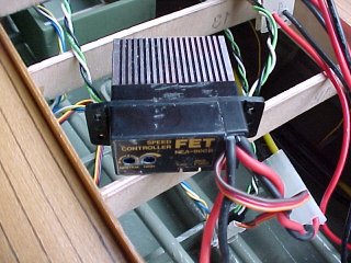
My existing speed controller died, January 2004, b#$%er, and I couldn't get parts to fix it! This controller was used to control the two bottom motors. I had this controller quite a few years though and it's been in a plane and a couple of boats and has served flawlessly but it operated at the receiver pulse rate of around 50 Hz and with big motors and clunky gears, in a boat that is a great sound box, it made for a very noisy boat, in fact I've was told a couple of times "You're not allowed to use petrol powered boats in that lake"!
Hey but it's a PT Boat it's supposed to be noisy (and if only the rocket launchers were operational!)
January 2004 The New Speed Controller Design Starts
Speed Controller 1
This is a circuit for a fairly simple "high rate" speed controller that I found on the Internet and I modified it slightly and added a test oscillator using the spare op-amp (dual's) and I have included a BEC (Battery Eliminator Circuit) which is basically a voltage regulator which feeds +5 Volts (preferably make that +6V) out of the servo connector to power the RC receiver instead of having a separate receiver battery pack which is quite a common feature in commercial units.
See www.math.niu.edu/~behr/RC/speed-ctl.html for Eric Behr's website and the original article by Keith Walker "A miniature high-rate speed control, from the newsletter published by Electric Model Flyers' of Southwestern Ontario". This controller was for model airplanes so it doesn't have, or need, reverse, (most high end airoplane controllers also have braking so they can force a foldable propeller to stop rotating and fold up)..
The overall design goal for my speed controller project was to build three separate "high rate" speed controller complete with a rudder mixer function that uses "through hole" techniques (non surface mount) and also uses fairly cheap and available components so that anyone with a degree of skill can build it themselves for a much lower cost than the equivalent commercial unit and also tailor it for special applications. For this reason I will not initially be using a PIC microcontroller like many other "current" controllers as many constructors have no way of programming them. In any event for a boat as large as 1200mm long we don't really need to squeeze everything in to a tiny package and unlike airplane controllers we're not that worried about weight or things like electronic braking, we just want efficiency and grunt!
In theory if several controllers are combined together, quite a number of parts can be shared between them, and my plan for "boat 2" was to have three motors (one for each prop shaft) and three separate battery packs to increase the boats running duration and efficiency and to reduce the overall current flow through any particular wire/connector to both reduce resistive heat losses and also the risk of fire. I will use a 4th small battery pack for the motor reversing functions instead of using a vast array of expensive MosFET's in three "H" Bridge reversing setup's - this has the potential to reduce the overall cost dramatically and also increase the boats forward performance to boot.
This is a basic and very common "H" bridge reversing motor control circuit with 2x N channel (bottom) and 2x P channel (top) MosFETs (arrow shows current flow for "forward" operation). If we wanted to parallel multiple FETs for better "on" resistance and lower power dissipation we need to parallel all of them to the same extent and as power MosFETs are costly this is why most reversing speed controllers are very expensive.
(note: I have now designed a H Bridgesingle controller with BEC - below)
Basic Ohms Law Power Formula
Power (heat in Watts) = I squared (current in Amps) x R (resistance in Ohms)
Let's assume a biggish motor requires 20 Amps continuous running current and say 40 Amps peak if stalled and we have a single MosFet (or even a switch or wire or connector for that matter) that has an "On" resistance of say 0.008 Ohms (or 8 milliOhms) then we would have a continuous power dissipation in that device of 3.2 Watts, which is enough to make a TO220 (the package type) device very hot indeed at around 225 degrees C ( 64 degrees C temperature rise per watt) without a suitable heatsink anyway) and if the propeller gets choked with weed and the motor stalls, the current goes to 40 Amps and our single MosFET has to dissipate 12.8 Watts (800 degrees C), which is more than enough to melt silicon and destroy the device(s). The voltage drop across the single MosFET at 20 Amps is 0.16 Volts (or 160mV) and at stall is 0.32V and in a "H" bridge circuit we have two of these voltage losses, one on each side of the motor, which comes close to wasting 10% of a 7.2Volt battery pack. Putting two MosFET devices in parallel shares the current approximately equally and because the current is squared in the power formula, each device will only dissipate 0.8 Watts continuously (75 degrees C) or 3.2 Watts (225 deg C) if stalled. Putting 4 devices in parallel gives 0.2 Watts continuously (38 deg C) or 0.8 Watts (75 deg C) if stalled.
A further problem with the "H" bridge design is that it requires two such MosFET devices in a series circuit with one being typically a P channel device to keep the circuit simple and these in general use much more Silicon area to make and also generally achieve a worse or higher "On" resistance performance than N channel devices and as a result they are usually much more expensive devices. We could use N channel devices for the upper devices but we would then need to generate a positive voltage at least 5 volts higher than the battery voltage to operate them.
You may notice that "Voltage" does not appear in the power formula above and for a typical speed controller it is quite a different issue which relates only to the number of battery cells, the maximum currents into the motor and the breakdown voltage of some of the parts used in the controller circuit, however the wasted voltage drop across the controller FET's when it is turned fully on does affect the efficiency and maximum motor performance.
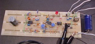
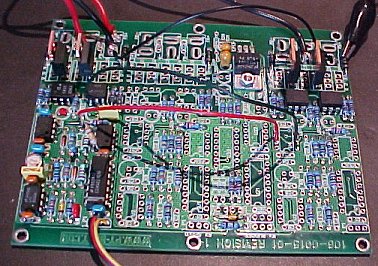
This is the basic speed controller set up on a bread board, I have one 60Amp MosFET a P60N06 which is quite impressive but I have some IRL1104's on order which are rated at 105Amps each with extremely low "on resistance" of 0.002 Ohms - almost perfect switches..
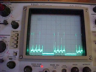
This is the sort of rubbish that comes out of brush motors, just look at those SPIKES! These are why you need higher voltage MosFETs.
In order to be able to drive three separated speed controllers I wanted to be able to isolate the output (high current) stages of the controllers to prevent possible unpredictable high current loops between circuits, this also allows us to run one or multiple batteries safely so I experimented with some designs, The opto isolator (or optocoupler if you prefer) device (4N35) can be inserted at various strategic parts of the circuit and in fact it is often at the front end at the receiver input but I chose to isolate just the output stage as I will be adding the other channel circuitry to the same receiver and battery eliminator circuit (BEC) voltage rails. I have also corrected a few items and changed a few values to make the settings easier. I changed the design of the test oscillator to make it more accurate and added some biasing to the servo input front end as my BEC brand receiver sometimes stops in a high state when the transmitter is turned off (or if it's batteries go flat) so the speed controller goes to a "full on" state, so now a "no signal" steady state input of either polarity turns the motor off, except for interference into the receiver, particularly when big trucks go past - hmm - I am going to need an FM radio and receiver.
Speed Contoller 2 (Forward Only)
I wasn't happy with the noise performance of these first two designs, very jittery when servo's are operated and also I needed to come up with a way to provide reverse operation and more than full throttle range to span forward and some degree of reverse. One of the issues with the oscillator in this circuit is that you can't guarantee the absolute levels of the tops and bottoms of the triangular waveform and to add reverse we need two sets of levels either one above the other with a gap for neutral, or two waveforms totally separate from each other, so I experimented with a CMOS version of the 555 timer IC (the original versions were often badly behaved) and this works very well!
In fact it gives the ability to change the oscillator frequency without affecting the settings, which may be useful later for getting rid of that annoying buzz that comes from the motor at low speeds and the 555 also increases the general voltage levels around the circuit to reduce the noise problem.
This design below is still rough around the edges but it does everything I want so far except not staying "motor off" when first connected or "transmitter off" as it has to go through the full reverse range to get to neutral. I have added the reversing section and my high efficiency "totem pole" output with two battery approach. I have experimented with various sizes of reversing batteries and the current plan even in the curent hull is a pack of 8 sub C's (3000mAH or better) so 9.6 Volt packs for forward per motor and a single pack of 4 sub C's (4.8V)for reverse. The other advantage of this twin battery approach is it allows the MOSFets to be biased from across both batteries in series which means that we can get away with lower "vgs" (gate voltage) spec parts and absolutely guarantee that they are turned fully on with minimum "ON" resistance. We will allow for 4 MosFETs in parallel for forward and 2 in parallel for reverse.
Speed Controller 3.
I did a bit more work trying to work out how to derive the opposing rudder mixer signals and also how to stop the speed controller from misbehaving when it's first turned on and I ended up with quite a different approach for the speed controller front end where I use the leading edge of the variable length receiver pulse to start a 1.5 milli-Second timer (variable for neutral position) and then use this timer output to determine whether forward or reverse pulses should be generated - my convention - longer than 1.5mS is forward speed and shorter than 1.5mS is reverse.
This dual path approach means that a single control voltage level signal doesn't have to traverse the full reverse range to get to neutral. The new circuit generates two, much higher, voltage levels from the servo signal that are both zero for neutral or no signal and they don't need any amplifying in order to operate the chopper amplifiers. I seriously fried the small battery holder I was using for the reversing battery and melted one of my oscilloscope probes on the very hot reversing FET when fiddling with the oscillator circuit so I decided to make the output stage absolutely unable to go into forward and reverse at the same time by putting the two opto isolators back to back from one chopper amplifier to the other so only one of them can ever be on at a time - gets rid of some parts and adds a major safety improvement - bonus! 😃
Speed Controller 4.
I'm very happy with this design, it works great, it doesn't suffer from noise and the front end section is almost exactly what I need for the rudder mixer function. I have gone back to capacitive coupling from the receiver and also added a zener diode to protect the CMOS parts from possible static issues a little bit better. I also changed the test oscillator to a cmos 555 timer - better and less bits required than the op amp version. I have no "range" or "full speed" adjustment as it doesn't need one and changing the values of R3 and R6 varies the forward and reverse voltage values quite readily. R5 and R8 set a small bias level to reduce the otherwise quite wide neutral deadband caused by the forward voltage drops of the 1N4148's. If I can find a readily available Low Drop Out (LDO) 6 volt regulator I will use it but for now I have gone back to 5V.
I thought at length about putting in a voltage doubler circuit to charge the smaller reversing battery from the main forward battery so that it doesn't have to be removed and charged but some research of available parts suggested that the cost of such an approach was quite high, however an unintended outcome of using the totem pole output design and the separate negative battery approach is that the current spike that is caused by the magnetic field collapse within the motor when the forward MosFET turns off at the oscilator rate at low speeds gets transferred to the negative battery by the protection schottky rectifier across the negative P Channel MosFET and this current pulse is quite significant. The same effect happens when in reverse, transferring the otherwise wasted magnetic charge to the forward battery. The other significant effect is that the level of the voltage spikes are also clamped by the batteries reducing the heat build up in the MosFETs due to their internal voltage clamping diodes, this difference is very evident in these two oscilloscope shots.
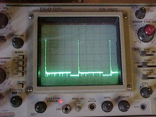
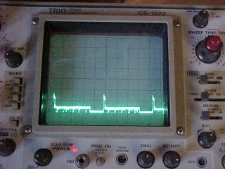
The left picture shows the voltage pulse from the field collapse in the motor being clamped by the MosFET voltage breakdown at around 50 Volts (which is still within spec, btw) whereas the right picture shows the clamping effect with the reversing battery connected at only around 15 volts.
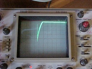
This picture shows the magnitude of the current pulse back into the negative battery, this is the voltage across a 1 Ohm resistor at 2 Volts (so 2 Amps) per division ( I have seen 10 -14 Amps peak) and 50 uSec per division. This pulse gets wider and taller as the motor is put under more load. I am using a non inductive 1 Ohm 50 watt TO220 resistor that is getting reasonable warm at low forward speeds so I know the actual peak current without the resistor is much higher than this, however as this pulse occurs only once per millisecond the average current measured on a multimeter is only around 5 - 10mA. The pulse gets smaller as the speed is increased until it is non existent at full throttle. I have successfully fully discharged the reversing battery and then let it re-charge using this method.
A theory only at this stage: If I have three speed controllers with three motors and three main batteries and I connect all of the positive battery terminals together, which I can do because of the opto isolators, I can get away with only one reversing battery for all three controllers and it will be charged by pulses from all three motors. If I use only one main oscillator they will all be synchronised!
The Rudder Mixer
This design works well, I have tried the approach of using the FM input on the 555 timer in the speed controller to vary the speed forwards and backwards and that also works well, I have put four resistors after the diodes (R23-26) so that the effect on forwards and reverse can be separately varied. There are two input connectors so that the rudder steering servo can be plugged in somewhere, so a lead from the receiver to the mixer and then one out to the servo.
I have updated the mixer section slightly and replaced the diodes and extra inverters with a quad analog switch as it saved room and it also works better.
There are two ways to operate the mixer, using the conventions above the boat turns in it's own length but if the wing motors are connected to the other sides or swapped the boat can 'walk out' from the dock sideways.
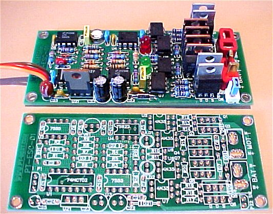
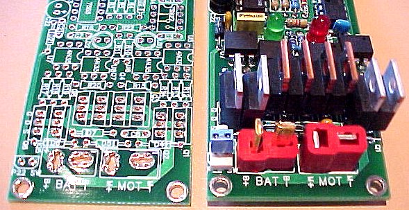
Once I have tested the pc board I will be offering it for sale either as just a PCB or as a complete tested unit. I ended up putting in 4 parallel Mosfets for forwards and 2 for reverse on each channel so it has enormous continuous and peak current handling capability and I fitted it out with "Deans Super or Ultra" plugs and sockets for all the battery and motor connections.
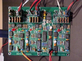
Voila! a minor stuff up with the Deans sockets being a different layout to the plugs and the steering LED's that I added went to the wrong rail but this is easily fixed and this controller seriously kicks Butt! I left out the reversing parts for the center motor because I can't justify why I need all three motors in reverse and it saves around $USD40 in parts. Even buying all the parts from expensive retail electronics stores the total cost adds up to around $USD300 which is quite cheap for three speed controllers with reverse and a rudder mixer
The only similar controller that I am aware of is the Vantec RDFR22 which is a dual H bridge controller with a rudder mixer and is around USD$270 and at 0.012 Ohms doesn't have nearly as good "on resistance".
This controller would also be great in a tank or any track vehicle or even in a wheelchair where the rudder mixer acts as the steering..
I built the following mounting rails for boat 1 which sits in front of the new 30 cell battery box.
Experimental 'H' Bridge Speed Controller
Here is a design that I did for a 'H' Bridge speed controller that gives forward and reverse from one battery, I have also done a PCB design for this at but I built the prototype using the existing PCB just to try out the design, I have added two more opto couplers in series with the existing ones and another FET output stage. I changed the pulse width chopper op-amps from an LM358, as it doesn't have the capability to drive two opto LED's in series, to a ST Microelectronics TS922 which has excellent 'rail to rail' outputs at up to 80 milliamps, great for driving multiple opto's, however it also comes with a very strange input common mode voltage issue that only let's the inputs get about 1V apart from each other so I had to drop the output voltage from the master oscillator (by adding a resistor (R16A) from the 555's FM input) to stop it charging both pulse detection circuit capacitors from current flowing out of the non inverting (+) input pins and then trying to go forwards and backwards at the same time. There are a few 'rail to rail' op amps about and I will try the Maxim MAX474 next but it's output current capability is not nearly as good.
The 'H' Bridge design built on one of the existing PCB's, basically just one complete controller circuit and two output stages linked together at the input of the opto couplers. Only one FET per circuit loaded at this stage.
This is the new single channel, single battery, reversible H bridge board layout and I am waiting for the prototype PCB's to come in currently, I have included a few slight changes which I will add to rev 1-1 of the triple controller if they work out OK, including the header P22 for a power switch and a couple of extra resistors, I have also re-jigged the routing shape file for the Deans Ultra plugs and sockets as they have fatter pins than the Super Deans versions.
THE NEW SINGLE H BRIDGE CONTROLLER IS NOW FINISHED
Here it is finished, the only issue is that the Fairchild 4N35 Optocouplers that I bought are a little longer than the previous brands that I have used and they are a bit of a tight fit but other than that it took a couple of hours to build and worked first time, the Deans connectors are a nice snug fit. I added 4 extra plated through holes to each of the deans plug pads for high current and better through soldering. The power switch connector works out well, it needs a switch, a couple of short wires and a 2 pin female header or as I have done here it can just be shorted with a PC style shorting strap. This design has an extra resistor fitted to the main oscillator FM input to sort out the front end issue on the TS922 op-amps and the CMOS 4001 quad 2 input 'or' gate is replaced with a TTL compatible input level 74HCT02 and an extra pull up resistor added to the receiver front end to fix the low output voltage problem from my new Hitech receiver which only outputs a 3 volt pulse for some dumb reason...
OK I have tried the MAX474 Dual op-amps and they work really well, so with those fitted instead of the TS922 the resistor values can go back to the originals as shown in the schematic above. I changed the LED resistor R10 to a 1K as the LED's use some of the available output current that would otherwise go to the opto's and they don't need to be that bright. The MAX474 gives around 18mA for the opto LED's.
For those that want dynamic braking instead of reverse, leave out MOSFets Q5,6,7 and 8, opto's U7 and 8, Schottky diodes D6 and 7 and resistors R17,18,19 and 20 and then connect the motor positive terminal (M+) to the battery positive terminal (B+) using the Q5 and Q6 pcb source (S) and drain (D) pad positions as well as pins 1 and 2 of U8 and you will have a very high efficiency car or plane speed controller. So instead of controlling one arm of the reverse speed, Q1 and Q2 will put a short across the motor to stop it spinning very quickly. The severity of this braking can be controlled by the throttle stick position in a similar fashion to the reversing speed control.
I will do a revision 1-1 of the triple controller PCB with the same changes and then they will then both be for sale as blank PCB's with schematics and parts lists and I will continue to look for the latest and greatest MOSFets with the lowest 'on' resistance and the lowest vgs (gate voltage) specs, particularly the P channel devices as they are not as good as the N channels yet..
I declare this section of the design finished (at least for now).
Well, never say finished - after messing about with a couple of brushless motor designs see the new brushless page I have looked at some very nice devices for driving high side N Channel MOSFets instead of using P Channel devices in the upper arm of these controllers, such as the Micrel MIC5018, the Linear Technology LTC4440-5 and the ST L6388, these all have high current gate drive capability generated by a charge pump that can make the gate voltage more positive than the positive battery rail to turn the device on. N channel Fets are more potent with less 'on' resistance and much cheaper than P channel devices. The other advantage would be that you could easily add as many of these devices driving as many Fets in parallel as you want without suffering a speed penalty from gate capacitance.!