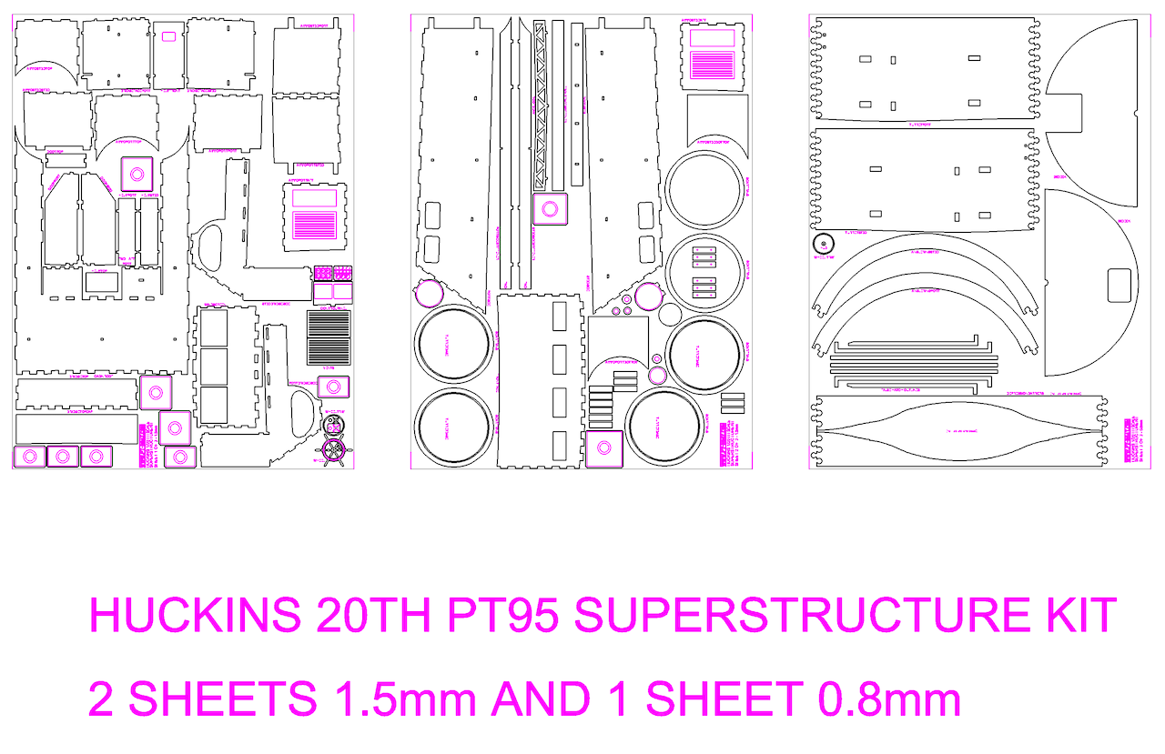
Huckins 78' (PT 95) Laser Cut Superstructure
This is the first cut of the Huckins laser cut superstructure November 2024.
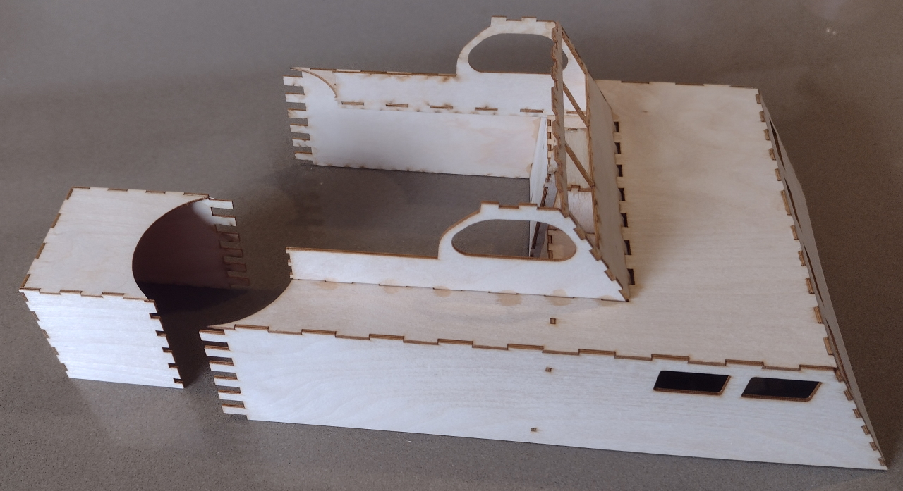
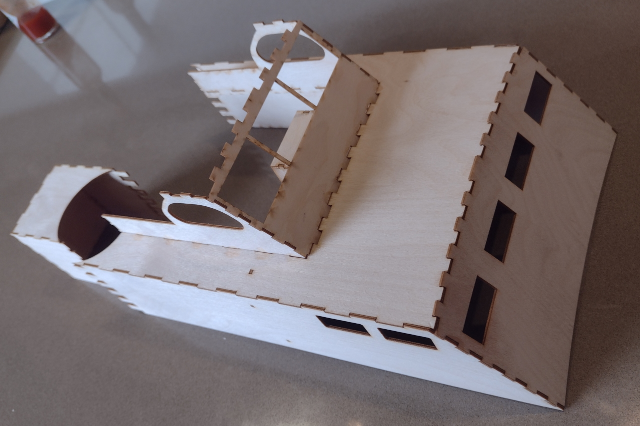
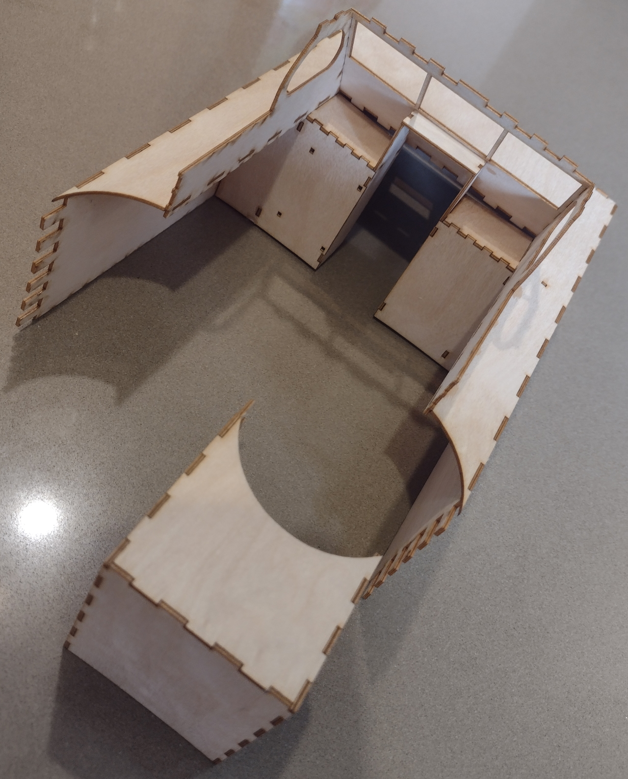
For version two I have changed the way I did the "benchtops" in the bridge area and I have extended the forward roof back to the port and starboard rear vertical panels as it's just too fiddly and too many bendy ply bits to put together, this will mean that they will be slightly curved but it will be much more solid and hey it's a model! The left side will be covered with controls and the steering wheel anyway!
My first machine gun turrets didn't work out very well and split where I had put too many alignment holes in, to line up with the straight superstructure side panels and the ammo storage boxes at the rear of them, I was trying to avoid too much filling but it just doesn't work, so I removed most of the alignment holes and it worked much better as you will see below. I also cut cut a rectangular panel and rolled it up to make a "forming" tube, rolled it up about the same diameter as the turret and then I taped it up with some masking tape, or you could use elastic bands or zip ties, I also found a straight sided cup about the right diameter and that worked will also.
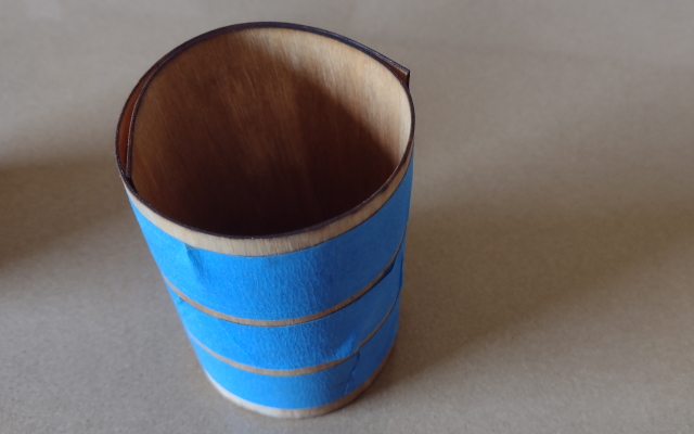
I then rolled up the turret piece and put it inside this tube, put both in a fairly large cup and poured boiling water in, this allows the 0.8mm (1/32") birch ply to relax and take on the tube shape. You could also steam it or soak it if you prefer, sometimes I put things in the microwave after this soaking but that usually ends up badly with wet birch ply as it becomes a bit conductive. A normal convection oven works well on a low heat!
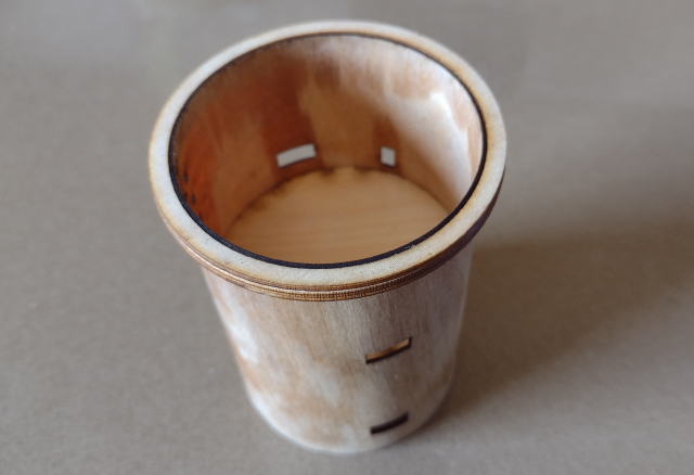
So I then dried out the ply a little, while still in the "form", then took it out and pressed it together at the jigsaw zip joint, put the three layers of scarf ring around the flat top and put in the solid bottom disk, this keeps it all nice and round.
I also put another solid disk temporarily in the middle just to keep the shape and then glued it together down the zip join. Don't glue the top scarf rings (three on each turret) on just yet as you will need them for the next stage!
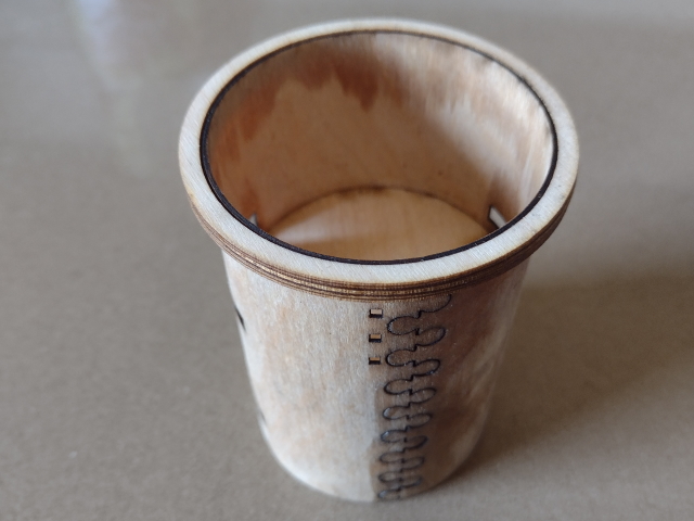
You can see that the jigsaw joint works very well (I have used this method on quite a few models now) and with a bit of filling and sanding it will disappear! Ah, I meant to get rid of that middle little hole (in fact I messed up the location of those three holes altogether - fixed now)!
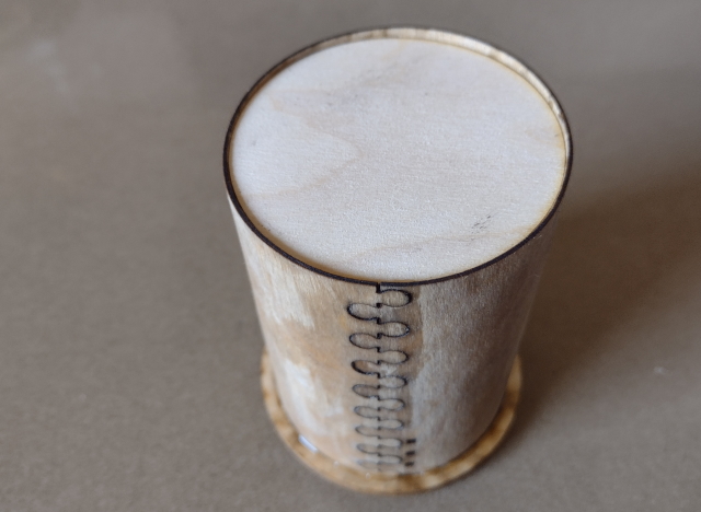
The bottom disk glued into place just a little up from the wavey bottom that should hopefully match the deck curve!
I spent a lot of time in AutoCAD and in Fusion 360 making sure that all the slots are in the correct locations and working out the deck curve and it was worth it! Happy with that!
The 2nd Version
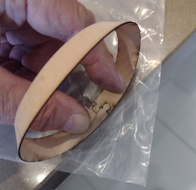
Making up the turret angled ring. Line up the jigsaw joint and press it down on a flat surface over the corner of a polythene bag and apply super glue.
This little angled ring caused me a fair bit of design grief but it worked out well first time, just make sure to push the joint together well!
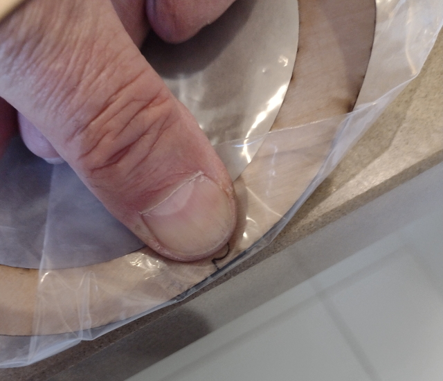
Fold the polythene bag over the top side of the joint.
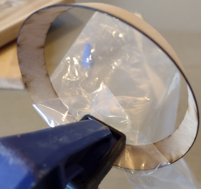
Clamp with a vise grip for a few minutes. You will find that the polythene helps the superglue set and usually means you don't even need to sand the join!
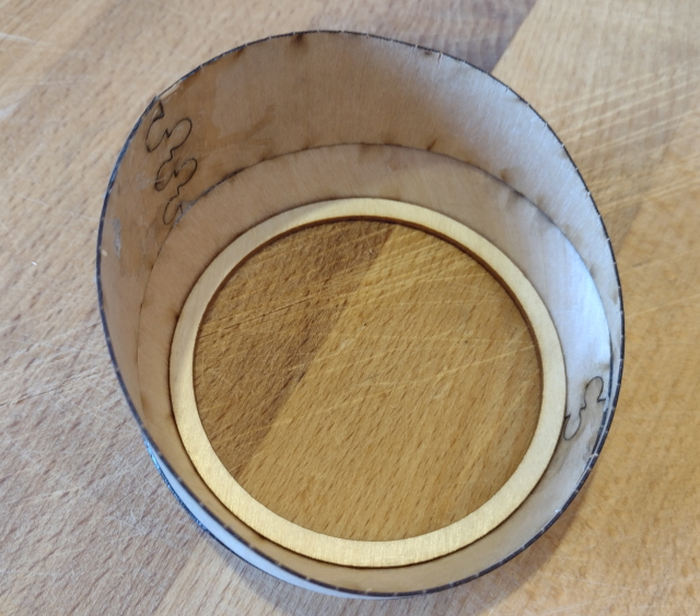
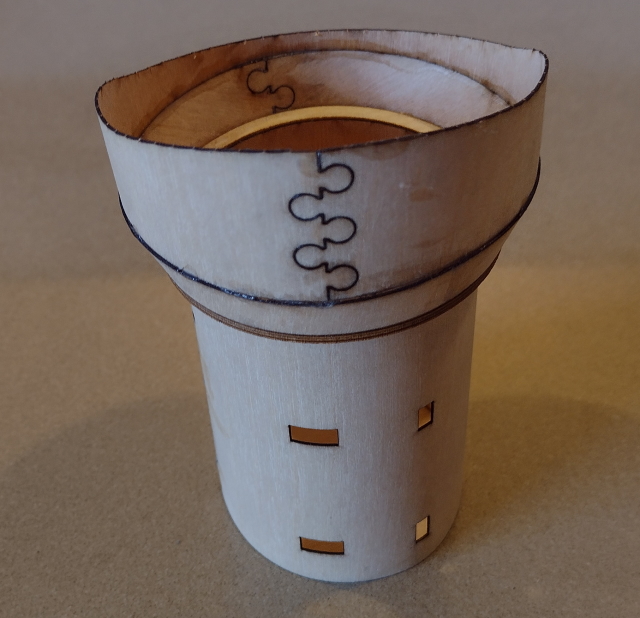
After gluing the top "depression ring" together the same way as the angled ring, I have glued it onto the top of the angled ring by tack gluing it in a few places first and then more places, until you are happy with it's position, then all the way around. I have also pushed one of the scarf rings (three on each turret) inside the bottom of the angled ring and glued it in place, the main turret body tube will come throught all three scarf rings and should end up flush with the top surface of this one. The machine gun rotating scarf ring will revolve around on top of this surface (or be glued in place).
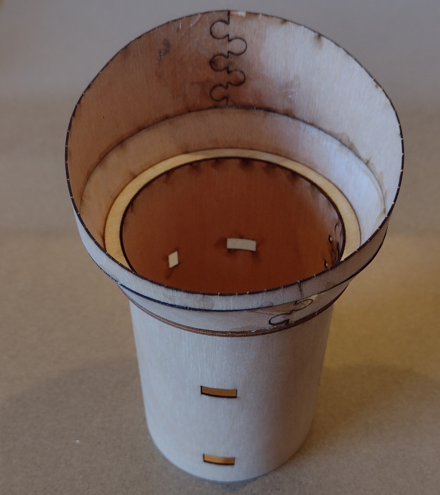
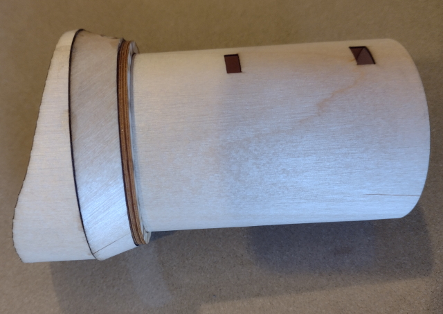
Tah Dah!, an almost finished turret - beware though, don't glue the top part to the bottom tube until you have made up the complete superstructure or, as I have, you may glue it on the wrong way around!
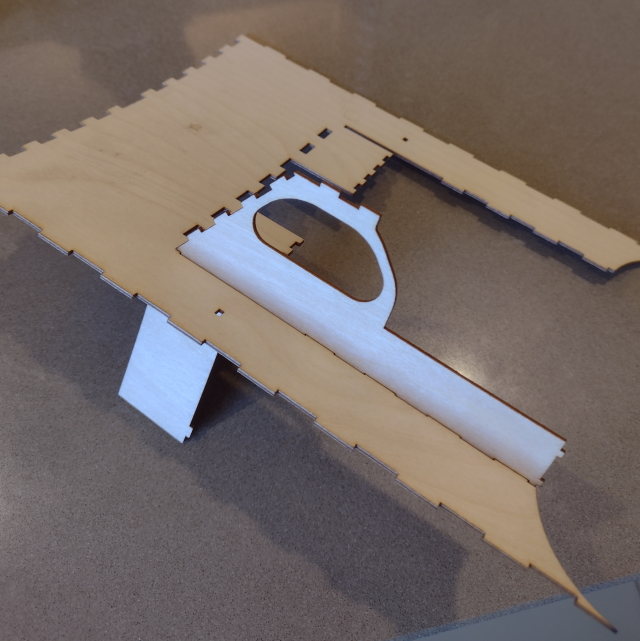
This is version two of the main superstructure, which is much more accurate than version one, as I have put it together (virtually) in 3D, adjusted the fit and then exported it back out to AutoCAD to correct the cutting files.
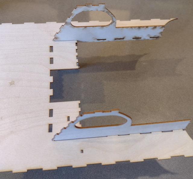
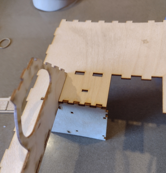
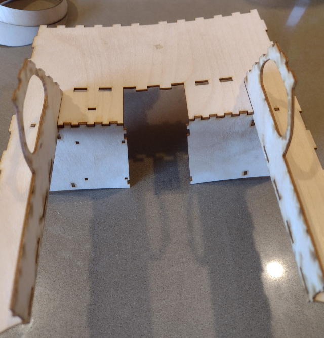
You can see in this photo that the roof wants to curve in the opposite direction to how I want it to curve!

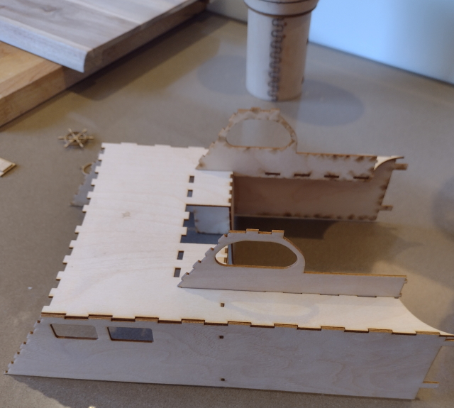
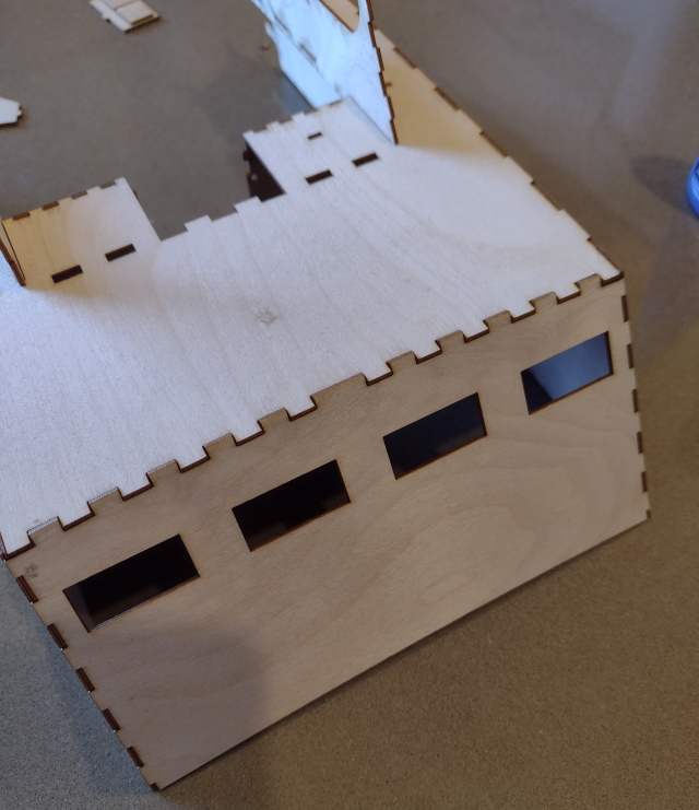
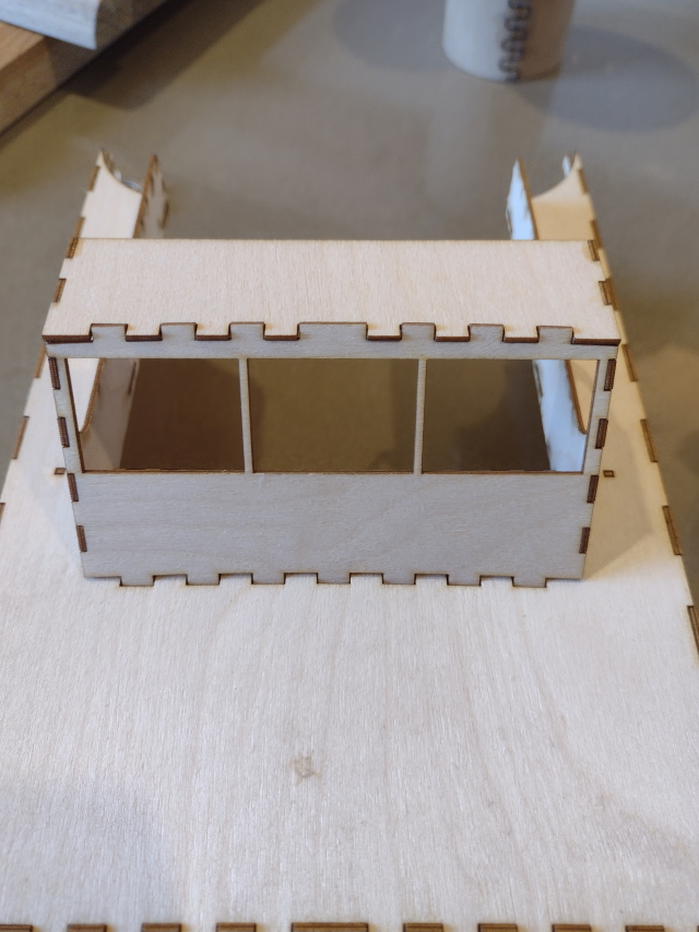
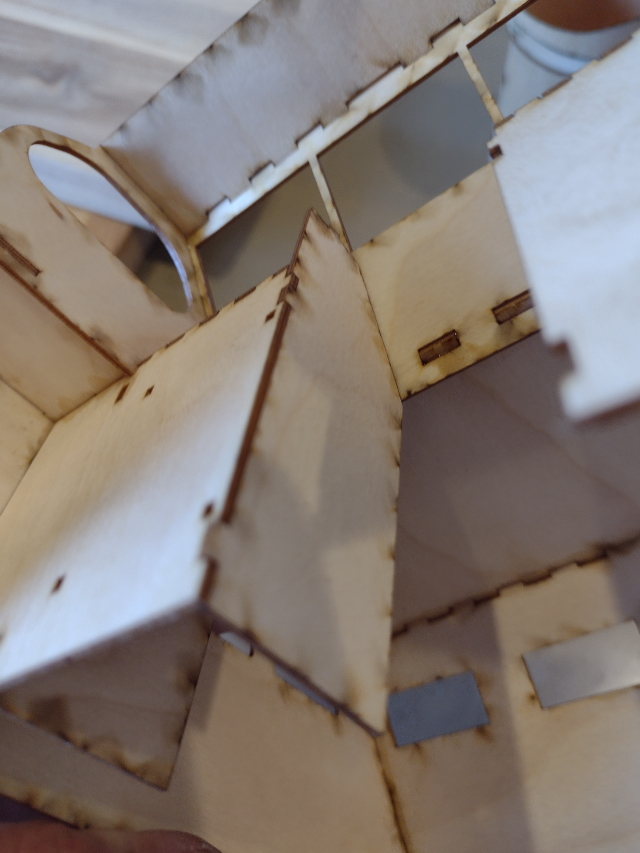
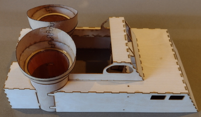
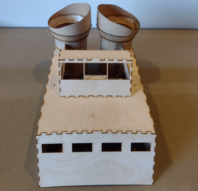
V2 looks pretty good now! all the corner adges need to be radius'd sanded and filled and then sanded again and then a coat of paint.
I am very happy with the fit but there are still a couple of issues that I need to sort out, one of them being the bendy plywood, I have added a side panel stiffener to stop those bowing outwards and an internal truss roof beam, between the side windows, to force the roof to bend the way I want it to bend and there's a few extra detail bits such as the air grills on the rear of the ammo boxes - behind the turrets, the steering wheel and it's mount and the engine gauges at the helm.
I have also put a brace across the bottom of the door into the radio/chart room to straighten up the panels there as it's all a bit too flexible at that point and will affect the fit of the superstructure over the "upstand" either side and at the front of the hole in the deck. The upstand is there to hold the superstructure in place and also stops water from finding it's way inside the hull when running at speed.
