Schnellboot Depth-Charges
(for the German S-100 Class Schnellboot (Fast Boat))
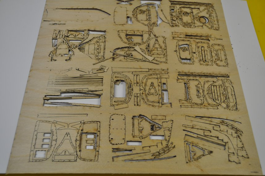
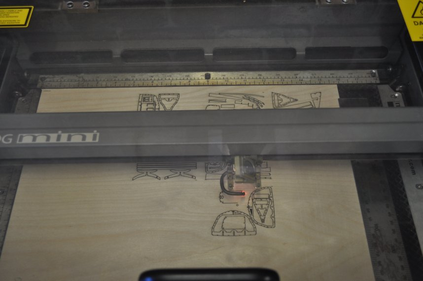
I cut a 100th scale version of the SBoot for Sebastian in Germany, the whole kit fitted on one sheet of very thin ply and I am waiting for Sebastian to tell me how well it worked, apart from a few pieces falling out in the bottom of the laser cutter it came out much better than expected.
I have re-designed the entire keel to get rid of the need to shape a long length of spruce and also so that it has a well defined edge to glue the hull planking to the keel as I wasn't happy with the way that I did it before.
I have also redesigned the motor mounts to use a larger variety of motors and motor mounts.
January 2016 - Covering the SBoot hull.
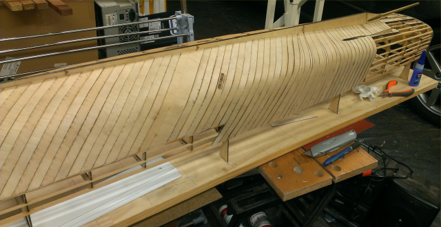
I put in some hours over the Christmas period and January on the Sboot hull covering.
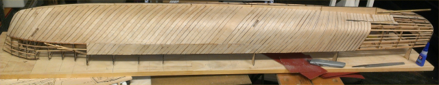
This shows one side almost covered.
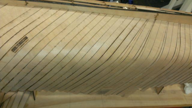
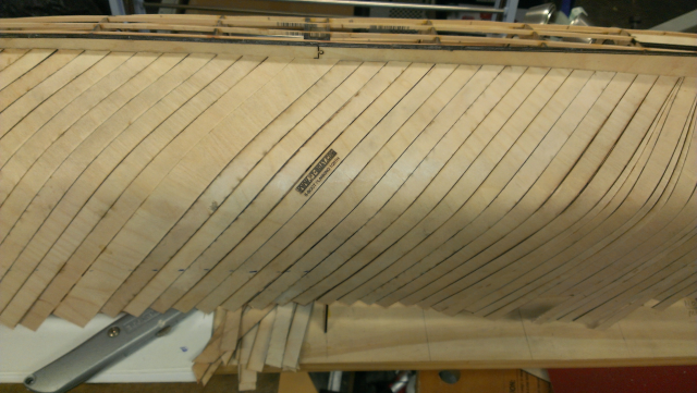
There are a few planks and lots of glue!
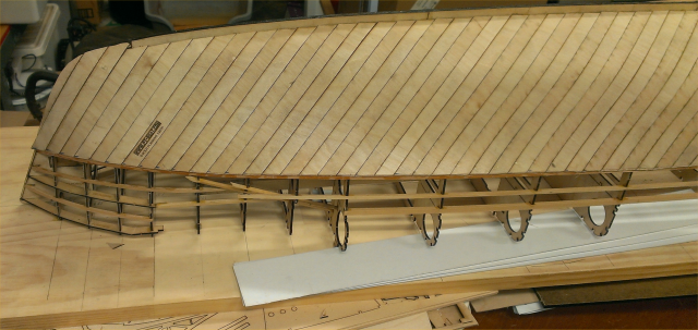
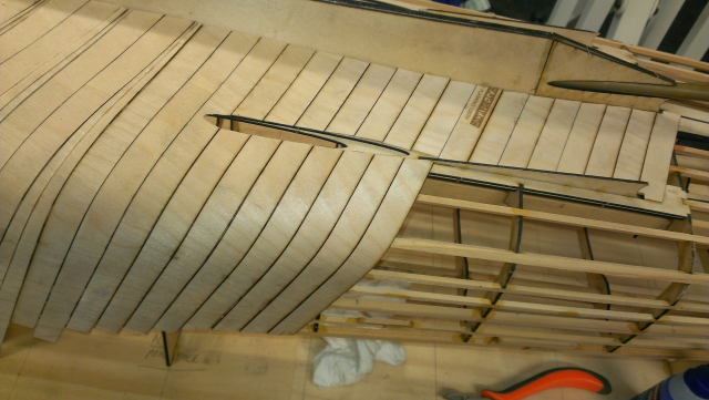
The keel emerges from the planking around rib 18, once the covering is complete I will smooth it into the hull shape.
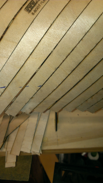
Towards the stern the sides blend into the bottom so the covering strips can continue from the keel to the gunwales, forward of that they need to be cut and joined.
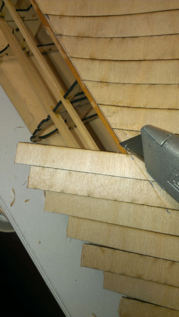
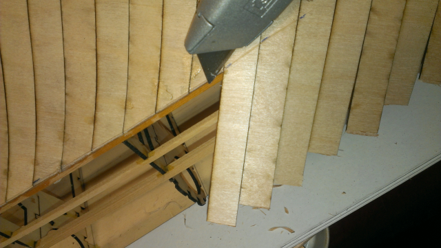
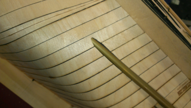
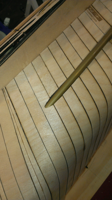
I found the angle of the planking strips was too great and it was difficult to get them to lay flat against the frame the further aft I went, so I cut some strips diagonally lengthwise and used them as wedges and gradually changed the angle, which you can see above the Stanley knife (box cutter). On the other side of the hull I will lay the strips almost square to the keel as I believe this will help with that problem. what I was trying to do initially was have each strip join at least two frames, for maximum strength.
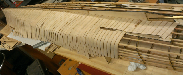
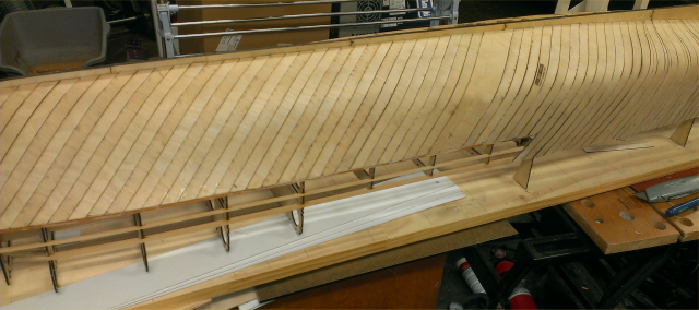
Hmm, starting to look like a boat (boot)!
April 2015 - Building the new SBoot hull kit
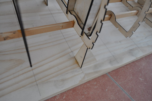
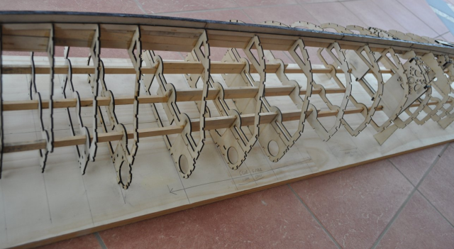
The 1/20th SBoot hull is built on a 1800mm (6') long by 300mm (1') wide pine board. I marked a centreline and then drew a line across where each rib locates.
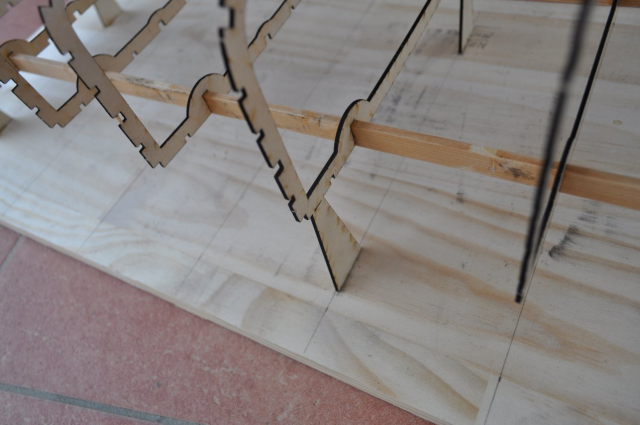
As the bow section is higher than the aft deck I have added stands to three of the rearward ribs so they can be glued down to the board.
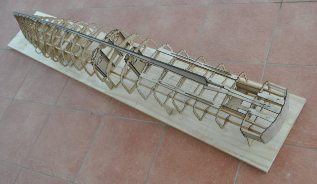
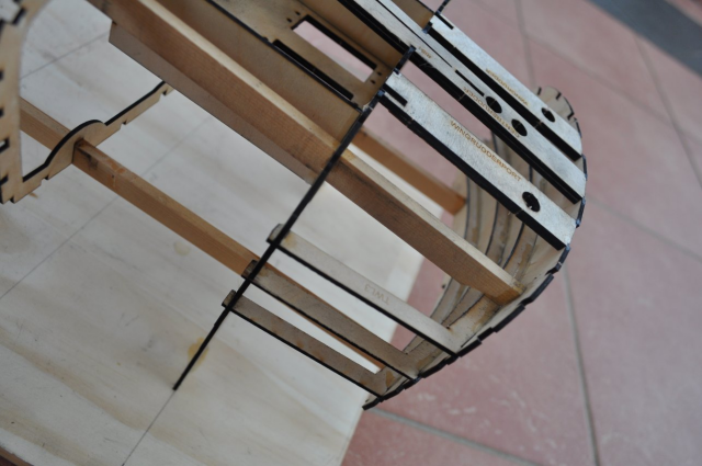
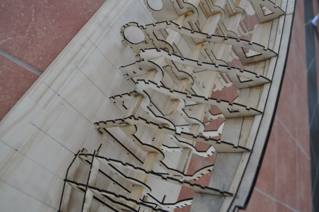
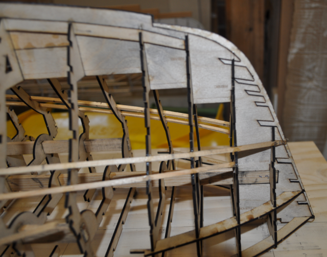
The stern is curved so there are three frames plus the rudder stiffeners and long main runners holding it in place.
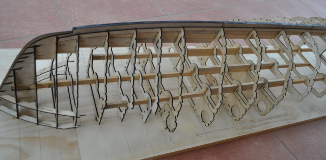
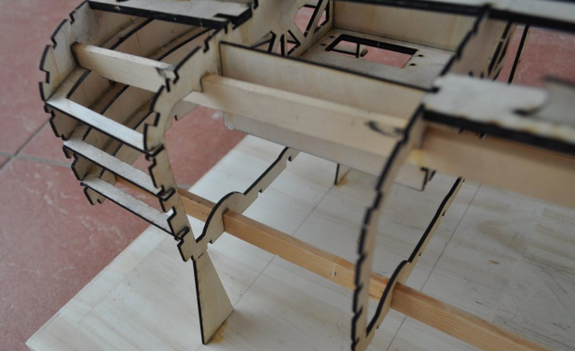
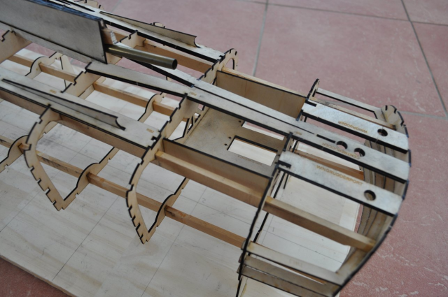
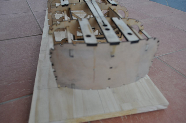
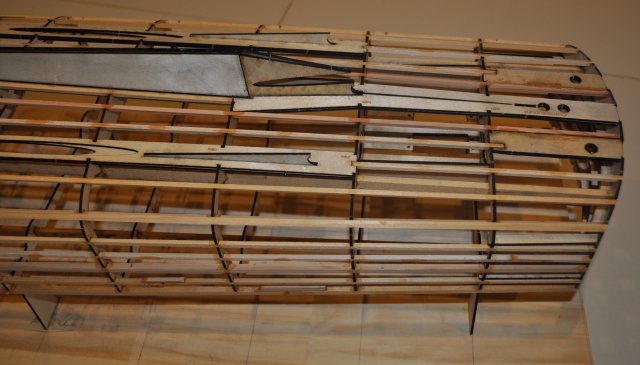
The front 1/3rd or so showing the torpedo tube holes.
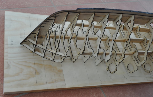
The bow section.
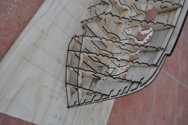
The bow section showing the cutouts in the keel for the stringers and the deck edge pieces which help to keep it all straight.
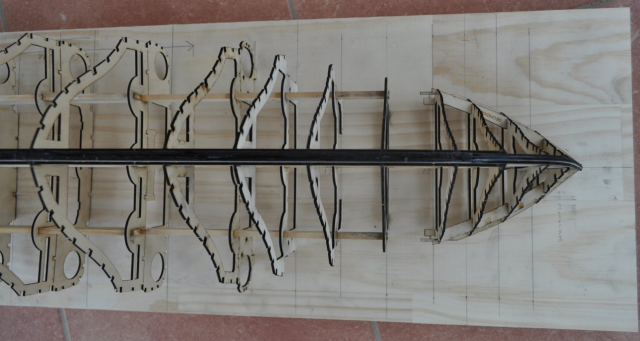
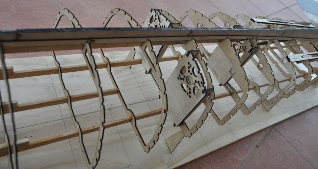
A view from above showing the extra ribs at the bow, all main ribs are 90mm apart but there is an extra rib between 16 - 17 and 17 - 18 and two extras between 18 and 19.
Oops I misaligned these ribs a little! For the giant Cobra motors that I have bought I will need to cut a piece out of the keel to clear. I am considering moving the centre motor one rib further forward.
The centre motor mount.
Even the best of us manage to glue things on upside down. The Loctite professional superglue is so strong there was no way it would come off so it will just have to stay and I will fill the missing bits.
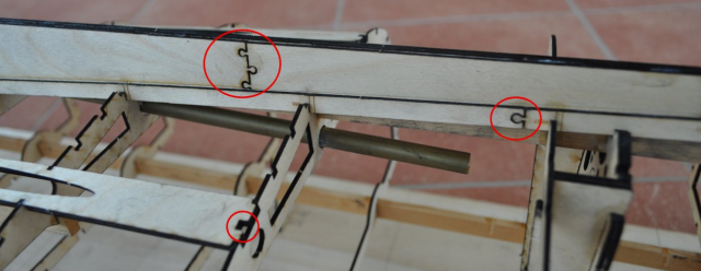
This picture shows the jigsaw joins in the keel sides and the recess(s) in the wing keel pieces to take the end of the stringer.
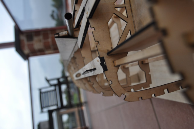
The centre prop shaft and where it emerges from above the main spruce keel. The angled keel end pieces are not in place yet, they fit in the V shaped slot showing below the shaft.
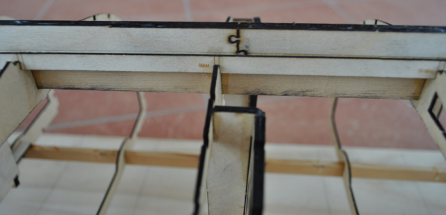
The Keel flares out aft from about rib12 to form a V shape for the centre propshaft to come through. I added an extra runner along the top of the keel for the hull covering to fit to.
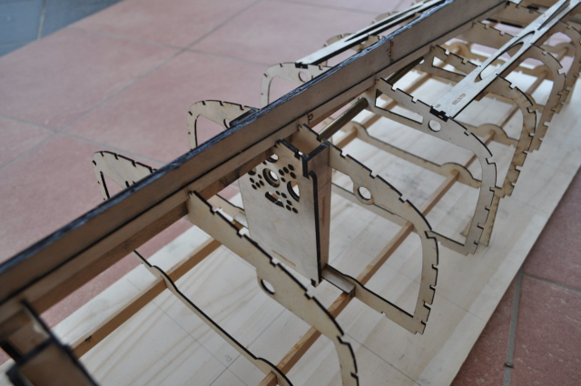
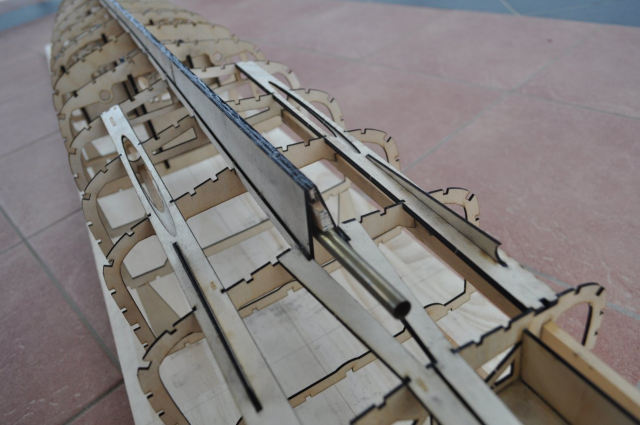
I've possibly got a bit carried away with the number of stringers, I've added an extra one in between all the existing ones but it's going to be very long and I am concerned about tortional strength. You can see the stands holding up the rib with the wing motor mounts on it.

This picture shows the centre propshaft and motor mount alignment.
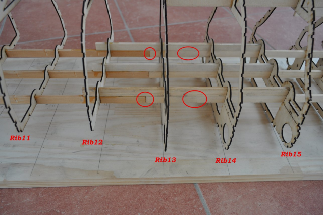
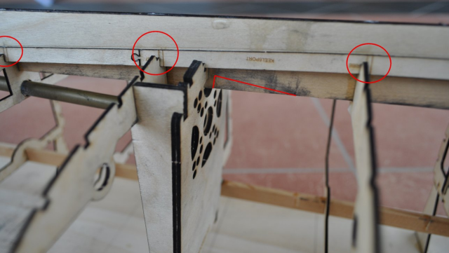
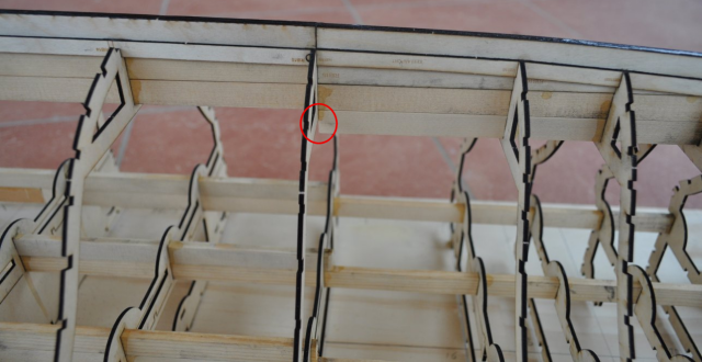
I joined the long spruce deck runners one rib too far back between ribs 12 and 13, the join should have been between ribs 13 and 14 for maximum strength, I'll add a lamination either side of the stiffeners between the ribs. I will get rid of the join in the centre deck runner as it doesn't go all the way aft anymore so it doesn't need to be extended.
The keel is stepped down at ribs 15 and 13.
This shows one of the jigsaw joins in the keel side pieces.
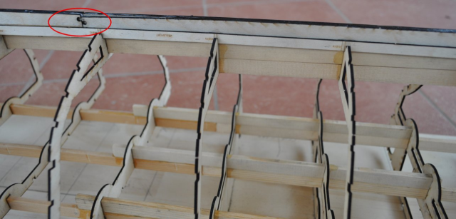
These three photo's show the legs that keep the hull rear up off the building board, they are cut part way through to easily get them off later.
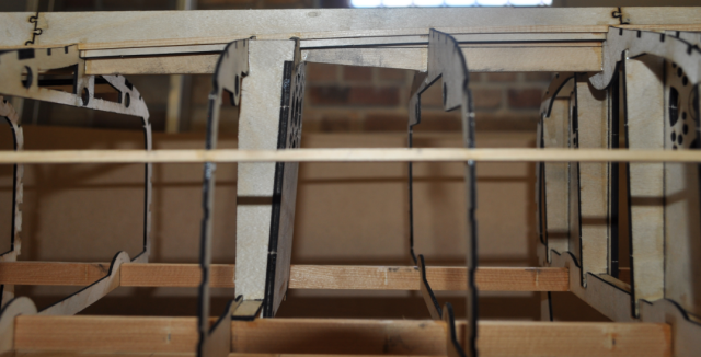
These two pictures show the stern assembly including the steering servo mount which allows for 3 servo's. I want to experiment with the "Llursen" effect by varying the three rudder angles, this added a few extra knots to the original boats speed.
I added an extra spruce runner either side of the servo mount for strength.
The Y shaped rudder stiffener in the centre allows either side of this piece to bend as it goes forward and follows the contour of the hull, it also provides a V shaped slot for the aft of the keel to fit into.
I was trying to show the alignment of the hole for the wing propshaft.
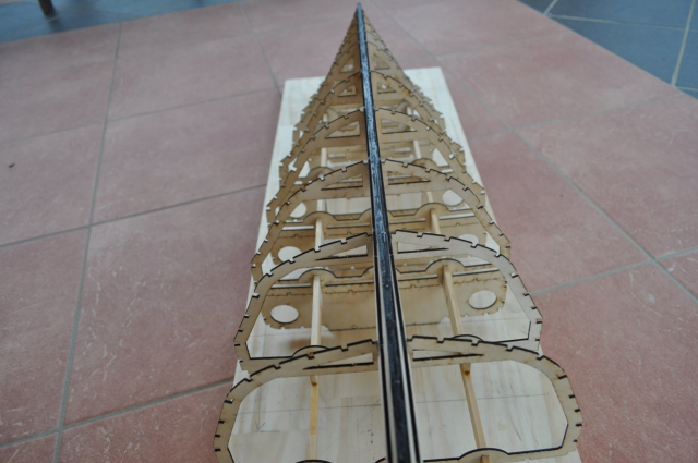
The keel is made up of a combination of laminated ply and 4' long spruce runners that all come together to make it incredibly strong.
This is the inner Stern frame, this will be covered by another layer once all the framing is in place.
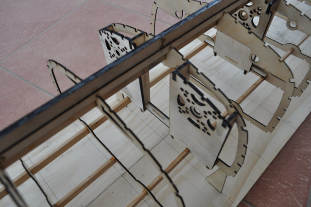
This picture shows the wing motor mounts.
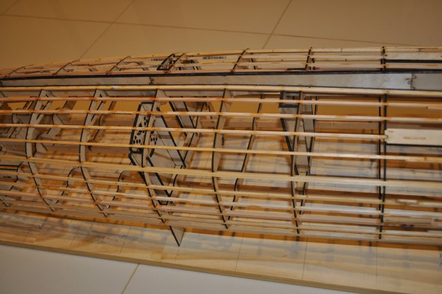
OK now I can add all the stringers!
Before I do that I needed to cut out a section of the keel where the centre motor fits, as the Cobra motors that I am using are 50mm diameter. I also decided to modify Rib 8 and added another pair of centre motor mounts so that the centre motor can be moved forward one rib if preferred.
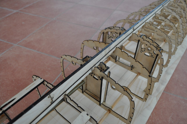
To start the stringers the bow end needs to be tapered to fit against the inner bow keel in the cutouts in the outer bow keel as shown below. The lower stringer shown below stops at Rib18B.
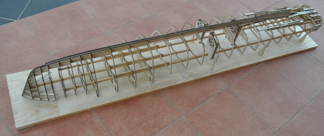
May 2015 Adding all the Stringers
Quite a few hours, a couple of bottles of superglue and many pieces of 1/8" x 1/8" spruce and 3/16" x 3/16" spruce stringers later I have almost completed the hull frame except for the topedo tube cutaway. I am very pleased with the final design, there have been a few slight issues along the way but I have corrected them as I go.
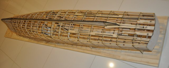
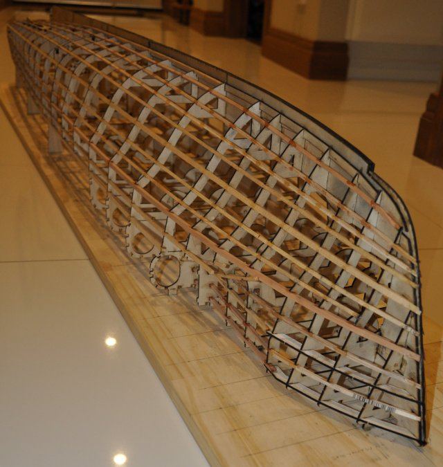
What am I going to cover it with?