Operational 1/20th scale US Navy WW2 21" Mk18 Torpedo Tube
The modelling objective is an operational 1/20th scale WW2 US Navy Mk18 Torpedo tube. This was the torpedo tube used on PT109 and other similar vintage early war Elco PT boats prior to the fitting of the much lighter Roll Off Racks and the use of shorter, faster and lighter aircraft style 22" diameter mk13 torpedo's.
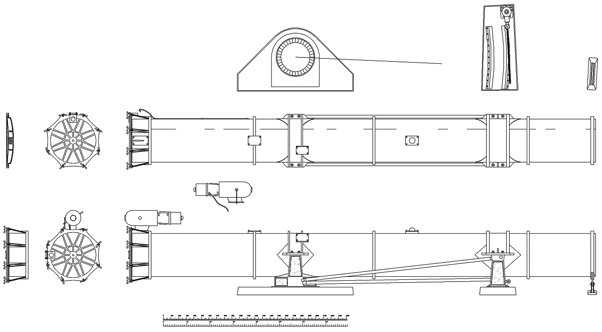
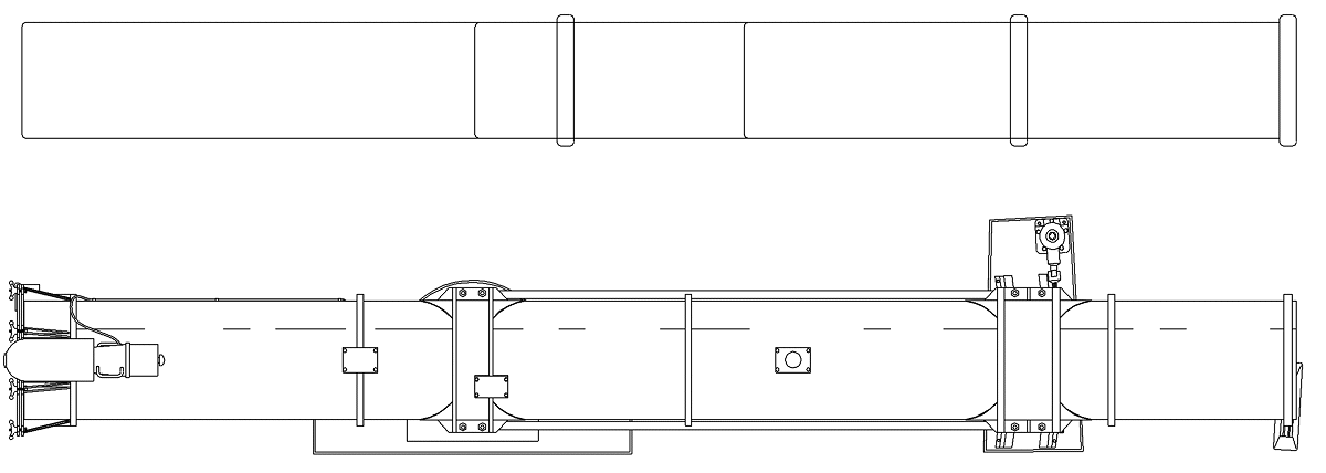
Top and side views.
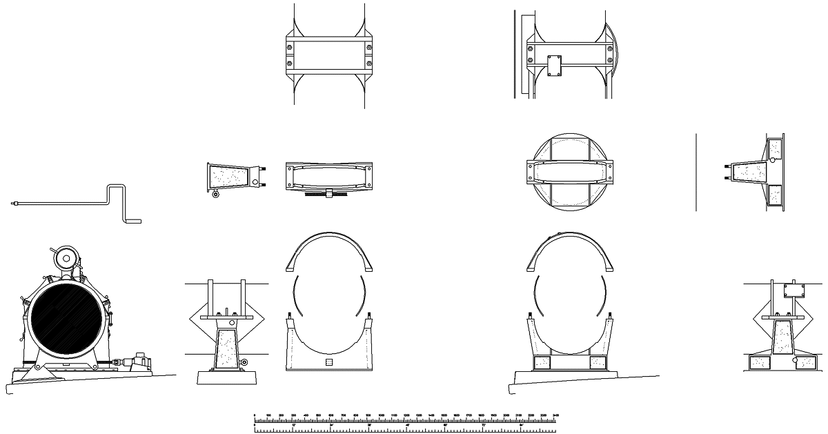
Various views of the tube and support saddles.
The end view (bottom left) shows how the "training gear" operated, the handle (above that view) was used vertically through a right angled gearbox to operate a horizontal transverse screw thread which moved the front tube saddle in a curved slot in the front main deck support, there is also a locking support fitted to the deck under the very front of the tube and two aligning holes in a locking plate fixed to the bottom front of the tube. A locking pin was fitted in either of these hole positions when the tube was either in the stowed position or "trained" out to the firing position. Training was required to allow the torpedo's to clear the deck when fired and additionally to allow the rear torpedo to clear the rear of front torpedo tube.
The "impulse" unit at the rear top of the tube had a small replaceable explosive charge which, when fired, pushed the torpedo out of the tube and laiunched it on it's way. The impulse charge could be detonated electrically from the bridge or in case of electrical system failure it could be struck on a firing pin at the rear of the unit by the torpedoman with a mallet.
There is an excellent video by www.militaryvideo.com called - PT Boats of World War 2 - which shows a torpedoman operating the tube training gear with the handle. This video contains a few technical errors and some crappy music but for the serious enthusiast it is a must!
The 1/20th scale Model:
21" x 1/20th scale is 26.67 mm diameter which is the size that I mistakenly made my original Mk13 operational balsa wood and pvc pipe torpedo's, so much of the torpedo design is already done, however the torpedo for the tubes is a much longer version which allows for more weight and changes the balance point considerably.
I found some time ago that the 26.7mm OD (20mm nominal ID) pvc telecom tubing that I used fits perfectly in an aluminium Berocca tube (Berocca is an effervescent vitamin supplement tablet made by the multinational Roche, so they should be available world wide).
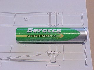
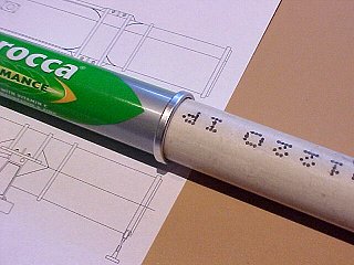
These Berocca tubes are a perfect scale fit and a perfect diameter, even the end 'fold over' is fairly right for the tube front so all that remains is to collect enough of them (12) to make up 4 complete tubes. They are easy to cut using a Dremel and a tiny cutoff wheel but protect your eyes, you only get one pair!
Top complete view and comparison with three Berocca tubes at 1/20th scale.
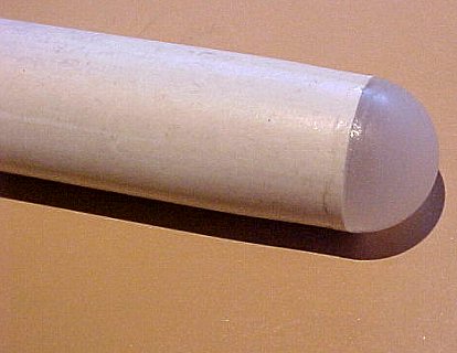
I also found that the ball out of a 'Mum' roll on deodorant is 1 inch or 25.4mm diameter and is easily cut in half and sanded to make torpedo 'ends'. If you heat a long length of pvc pipe gently and evenly around with a heat gun, paint stripper or similar device you can pull the ends apart and make the pipe slightly smaller in diameter where it was heated, then cut it where the diameter is 25.4mm, glue on the half ball and you have a very realistic tapered nose for your torpedo's.
Launching the torpedo with a tiny explosive charge is a possibility but will probably damage the torpedo's so compressed air is possibly a better alternative, although a puff of smoke just like the real thing does have a great appeal!
The tubes could be "trained" with a servo also but that may be more trouble than it's worth.
Reference: Torpedo Boat Manual 1st February 1943
Tube.
The tube proper is made of steel, fabricated by welding. It is pivoted on an
aluminum alloy turntable and turntable base. The forward end is mounted on an
aluminum alloy support which travels on corrosion-resistant steel plates and is
guided by brass Z-bars, cadmium plated. The turntable and the forward support
are joined with steel tubing rails. The tube does not recoil.
The breech ring and door are of aluminum alloy and are sealed with a neoprene
gasket inserted in the door.
Combustion chamber.
The combustion chamber is a steel casting, tested to 3,000 pounds per square
inch for strength and tightness. It is fitted with an interrupted thread piece
onto which the firing mechanism locks. With the firing mechanism removed, the
cartridge should slide into the chamber, when fitted with sealing rings under a
moderate hand pressure. The firing mechanism locks it in place. Blow-by around
the cartridge is prevented by the two sealing rings. It is
essential that these rings be in place, and free from cuts or gouges, to insure
gas tightness. A gasket is provided to keep moisture out of the chamber; this
gasket is not designed to prevent blow-by.
When the charge is fired, pressure is built up in the chamber and gas is fed
into the tube through a throttling orifice located between the chamber and the
tube. The tube pressure reaches a maximum soon after torpedo movement begins and
decreases gradually to zero as the torpedo clears the muzzle.
Firing mechanism.
The firing mechanism is designed for either percussion or electric firing,
depending on the type of primer used. The firing pin, which is insulated, is
wired to an electric circuit. When the striker bolt is in firing position, it
forces the firing pin against the primer, completing the circuit from the
control station. The primer may then be fired by hitting the striker knob or by
closing the electric circuit with the switch provided at the control station.
Tripping latch.
A projection to engage the starting lever is welded onto a small door over an
access hole cut in the tube. This is the tripping latch. The door is held
against its seat by four dogs. Guide strips extending aft from the tripping
latch to the breech to center the torpedo so that the latch and starting lever
line up properly. As these guide strips engage the boss on the upper rudder,
they also guide the rudder until it is clear of the latch.
Torpedo stop.
Torpedo stops are provided to keep the torpedo in place until firing, at which
time they shear. This assembly provides for two shear pins to fit into the
torpedo guide stud holes. With the rudder located in the before-mentioned guide
strips, and the tail hard against the breech door, the stop pins should fit into
the two forward holes of the four holes which formerly held the torpedo guide
stud.
Access openings.
There are, beside the above openings, two charging and access holes cut in the
tube and covered by small plates. One is for Mark VIII and
one for Mark XIV. There are in addition openings for setting speed and depth on
a Mark XIV torpedo. These openings are modifications according to Bureau of
Ordnance specifications.
Training gear.
Each tube is equipped with its own training gear. This equipment permits the
tubes to be trained inboard so that no part of the tube structure extends over
the rail. When action is expected, the tubes are trained outboard, by hand.
The training gear consists primarily of a handle-operated corrosion-resistant
steel screw which rotates within a swivelling cut made fast to the tube forward
support. A stop is provided on each screw which serves to fix the training
angle.
It is essential that the forward tube be fully trained outboard before the after
tube is fired.
Training stops.
At the muzzle end, the tube carries two lugs drilled with locating holes. A
fixed bracket, also drilled, is mounted on the deck. A removable pin is provided
for attaching the tube to the bracket, either in the outboard (trained) position
or in the inboard (stowed) position. The purpose of the stop is to relieve the
training screw of any load caused by lurching of the torpedo tube in rough
water. The pin should invariably be in place when the boat is under way.
When preparing to shift the tube by means of the training screw, make certain
that the pin has been removed. Bring the holes into exact alignment by means of
the screw before attempting to enter the pin. The pin should never be forced
into place, and will enter easily when the parts are correctly lined up.
For loading, the tube must be trained to an extreme inboard position, and in
this condition the locating pin will not be in use.
Loading gear.
One complete set of gear is provided on each boat to facilitate loading
torpedoes into the tubes. This gear consists of three dollies, a height gage and
a torpedo strap. The tubes are loaded one at a time, the same loading gear being
used for all of them.
The dollies are fitted with rollers and jack screws so that the torpedo may be
set on them, adjusted to line up with the tube bore, and rolled into the tube.
The height gage gives the height to which each dolly should be adjusted. It is
applied by dropping into the gaging hole near the center of the dolly. The strap
is provided to lower the torpedo onto the dollies.
In the loading procedure, each of the three dollies is to-be set on the deck,
forward of the tube, in the positions laid out for them and adjusted to the
proper height. The loading position of each tube is clearly defined by scribed
marks on the forward tube support and the Z guide bars.
Impulse Case
It is intended that 3" cartridge cases Mark VI be supplied for use with these tubes. The Mark VI case is identical in external outline with the 3" case Mark II, which was designed for 3"/23 caliber guns, except that it had been cut down in length to 6.60 inches. The Mark VI case carries the Mark XX combination primer, which screws into the case. If needed, satisfactory cases may be improvised from Mark II cases, by cutting off to 6.60 inches. The Mark II case, however, carries a primer Mark X or mod., which is arranged for percussion firing only. No attempt should be made to use any other cases than those referred to in the foregoing.
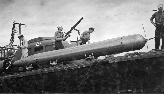
This looks to be an early Mk-VIII (Mk-8) torpedo being loaded on board PT21, using dolly's. The Mk-VIII torpedo had a spherical shaped nose of the front of the warhead, whereas the later Mk-14 had an elliptical shaped nose, that said, from many angles an elliptical nose looks to be spherical. This torpedo also has a very small warhead so is probably a mod 1.
More to come.