The Rear Mufflers
![]()
Mufflers were used by PT's for silent running by feeding the exhaust out under the water at low speeds. They each had butterfly flap valves fitted in the main exhaust pipes after the muffler take off which were operated by a lever system to allow straight through exhaust at speed or to direct the exhaust down through the mufflers to silence the boat at low speed.
The objective here is to make six mufflers that are operational and can be used to suck water up for use in cooling the motors, and other yet to be thought of idea's, such as squirting people!
When assembling parts note that we need three left and three right hand mufflers.
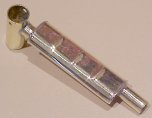
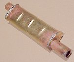
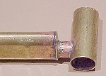
 The finished
muffler rear, polished and laquered.
The finished
muffler rear, polished and laquered.
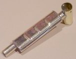
 Side view.
Notice the small hole for the flap valve, there is one on each side.
Side view.
Notice the small hole for the flap valve, there is one on each side.
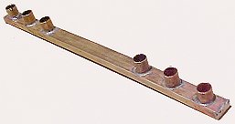
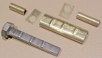 The various pieces.
The dimples are made by squashing a piece of round brass tubing in the vice over a filed down bolt with three ridges left to form the dimples, I used a piece of fibreglass PCB material between the vice and the brass so that the bolt could force the brass into shape but any hard flexible material will do. In this case I started with 3/8" or 9.5mm diameter tube but they could be a bit bigger.
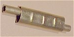 Assembled
prior to soldering, solder pipes in place before soldering the ends on.
Assembled
prior to soldering, solder pipes in place before soldering the ends on.
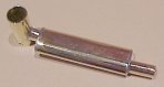
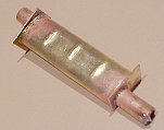 End caps soldered on.
 End caps
trimmed up with side cutters before filing.
End caps
trimmed up with side cutters before filing.
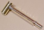
 Soldered into hole in exhaust pipe.
The Manifold
This is not an original PT Boat part it is to be able to use the water from the mufflers. It fits inside of the transom above the steering gear and the mufflers are glued into the short pipes with araldite to give a good watertight seal. The manifold is blocked in the middle to provide two separate halves for more flexibility, so that we can pump up one side and down the other, or up both sides and out the side of the boat.
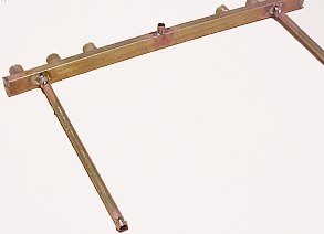
Note the 'olive' soldered on the end of the long pipes, this is to seal properly and to stop the flexible pipes falling off. The last thing we want to do is fill the boat up with water! These long pipes sit just below the deck to the sides of the Bofors opening so that they are not in the way.
It's a bit hard to see the manifold in this picture but it's a great shot of the steering gear and the excess flexible water pipes!
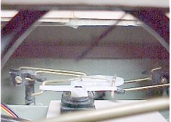
One problem is that 'at speed' the water behind the boat takes on the 'V' of the hull bottom and the inside 4 mufflers are not in the water. More study required! A right angled extension pipe could make a water scoop!
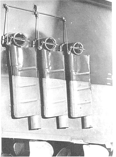
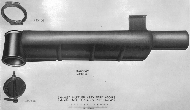
This picture shows the original boat mufflers, butterfly flaps and linkage mechanism. Note the brackets at the bottom of the mufflers that attach them to the transom.
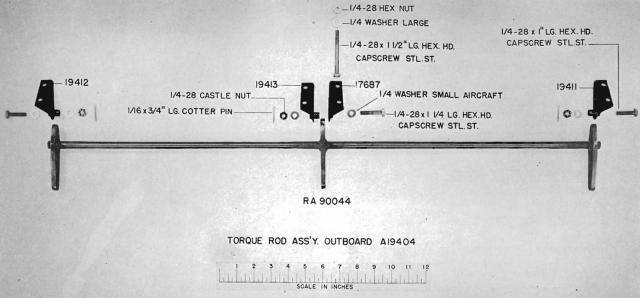
The linkage operation is fairly clear, there is a curved flat actuator coming through a vertical rectangular slot in the transom (looks like a cutlass) this pulls up on a lever at this side of a horizontal rod, the lever is extended and also attached to the vertical actuator rod down to the butterfly valve lever in the straight through exhaust section after the muffler take off and the horizontal rod also operates two more levers attached to the other two vertical actuator rods so that all three mufflers are operated at the same time. This is repeated on the other side of the transom for the three other mufflers.
This mechanism is quite well explained in pictures in a number of books, what isn't explained is how the thing was actually operated and I suspect the engine room motor macs (mechanics) would just have had a handle on the other end of the curved actuator inside of the transom in the rear Lazarette compartment aft of the engine room and it would have been operated manually, same as they did when putting the engine gearbox's into reverse.
I recently (2018) found some photo's of the original Mufflers and operating linkages.