Operational 1/20th Scale USN MK13 (MKXIII) Torpedo
2019 - 2025
2024, I am working on a steerable torpedo, so I can reliably get them to come back and as a part of that project (and also to make the torpedo more build friendly) I needed to create a new gearbox that sits further back in the after body, to make room for a tiny linear servo to operate the vertical tail fins.
The first prototype of this were received in October 2024 but proved too tiny and fragile to use for the steering mechanism and the clearances on the 3D parts was not sufficient to put the gearbox or shafts together, however I did manage to drill out the shafts and gears and managed to make it work without the steering part so at least I get a workable torpedo for my money.
This version works with the existing printed circuit board with a few modifications to make room for the tiny servo.

>
July 30th 2025 - The new version 2 parts are on their way from Shapeways/Maneuvo after a bit of to and fro about the forward propshaft being unmakeable in the material that I chose, which was a glass filled nylon, so I have ordered a few different materials to try.
I have done lots of research lately on the various methods to control the torpedo, as it sits just below the water. I have just about bought one of everything in my quest and I have landed on a combination of a new FRSky Taranis Q X7 transmitter and a new combined receiver and brushless ESC with a couple of PWM (pulse width modulated) servo outputs, these are designed for tiny indoor park flyers and drones.
Communicating to something underwater is difficult and a long standing thought I've had is to use an ultrasonic method but there are a few existing transmitter and receiver combinations for drones that have pushed the distance limits out to many miles/Kilometers and given that I am not likely to be more than a few hundred meters away, this "should" work. There is also a move away from 2.4Ghz transmission, due to congestion, back down to 900Mhz which will help and the FRSky Taranis transmitter can have a 900Mhz module and antenna fitted if ever there is a compatible receiver and antenna that fits in the torpedo.
The other nightmare in the RC field is the absolute plethora of different protocols used for transmission, so you can't just buy any old transmitter and receiver combination and expect it to work!
Then there is PWM, SBUS, FBUS and more at the servo output side, I'm sorry but as a electronics and datacommunications engineer for many years I find the whole SBUS/FBUS implementation to be quite foolhardy! What's the point of trying to get rid of lots of individual wires only to replace them with a heap of hydra cables to be able to plug in multiple servo's and other devices, it doesn't really save a thing, a BUS should be a BUS with insulation displacement connectors, or some other way of using only one cable, or don't bother. The nano servo's that I want to use don't have a SBUS or FBUS version anyway, they are still PWM and so are most of the ESC's'. So while the receivers are much smaller, I can't use them!
So I am planning one controller for the boat and another for the torpedo and operated by someone else!
The other reason for a redesign is that I can no longer get the small cylindrical 270mAH LiPo cells that I used in the last model so I have found some high discharge 250mAH LiPo cells and these have built in battery management / current limiting.
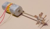
Steerable Version 2, fully working for the first time!!!
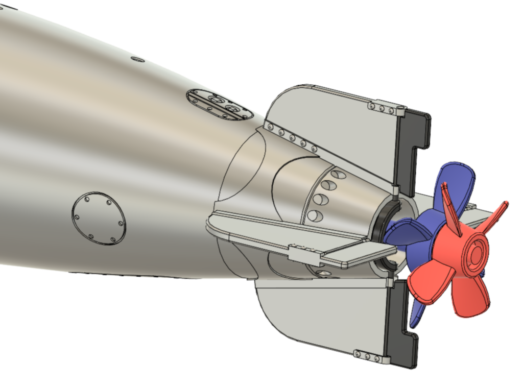
I have created helical gears for the gearbox to try to stop the propeller shafts winding themselves out of the body due to torque on the silicon rubber tube that links the motor to the rear propshaft. The idea being that a helical gear creates some thrust in an axial direction which should push the propshaft forwards? I am also making the gears out of brass to prevent a nylon melting issue and I have a need for more ballast!
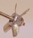
Steerable Version 1
The steering mechanism on version 1 was just too small to work as a 3D print and there were issues with the printed propshafts.
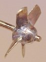
Steerable Version 2
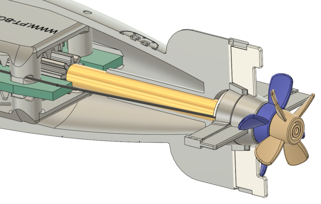
I moved the steering mechanism further forward, made the rudders bigger and redesigned the printed propshafts to have a brass tube between.
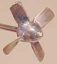
Steerable Version 3
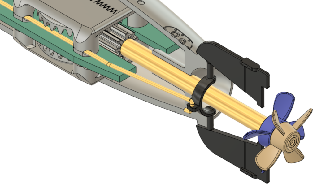
I moved the steering mechanism even further forward again to turn the entire vertical surface. This allows for more travel on the control wire so the servo doesn't overtravel.

2015
I am working on a new USN MK13-1 torpedo as the models below were quite difficult to make (just like the real thing I suppose). I have made up several prototypes based on the work I did for the Schnellboot torpedo. My aim is to make 1/20th scale 3D printed bodies for all models of torpedo used on PT Boats (USN Mk8, Mk13, Mk14 and Mk15) and Schnellboot and a printed circuit board for the inside, similar to the one I did in 2003 (below), which is identical for all models of 1/20th scale torpedoes but just has a different routing pattern (outside board shape) for each model, this necessitated re-doing the MK13 as it is the shortest torpedo that I intend to make and the existing MK13 board is currently the same width as required for all the others and fits in the 26mm carbon fibre tube that I have for the 21" models, mainly because the carbon fibre tube has a thinner wall thickness.
The new design is based on a single brushless motor with a direction changing gearbox to gain the counter rotating prop function. Brushless motors have so much torque that the losses from a gearbox are easily overcome. To use a brushless motor, a brushless ESC (speed controller) is required, fortunately with the emergence of tiny brushless drones, tiny ESC's are readily available that will run off 1, 2 or 4 cell LIPO batteries and they are also quite cheap. That all sounds very easy BUT a brushless ESC needs a remote control receiver to operate, in order to control the speed of the motor. I have spent some time on a very small footprint CMOS 555 timer that emulates the receiver signal and gives us speed control within the torpedo, this receiver signal emulator can also be made to return to the neutral, motor shut off position with a magnetic reed switch so that we can shut the torpedo motor down until it leaves the torpedo tube or alternatively rolls off the "Roll off Rack" when it then leaves the influence of the magnet(s) and switches to the set speed.
I have some very small 270mAH LIPO cells and two of them make up a very useful 7.4V battery that is extremely lightweight - in fact I have a problem because the whole assembly is so light that I am going to have to add weights in the front and rear bodies to achieve neutral bouyancy, a very good problem to have!
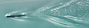
These new model torpedoes have so much thrust that they can lift themselves clean out of the water!
I have (28th January 2019) ordered 3D prints from www.shapeways.com for the German G7A and the USN Mk13-1 and once I receive these and make sure they are OK you will be able to order them from Shapeways! The insides may take a little longer!
Historical Data
USN MK13 Torpedo Specifications:
Length Overall -13' 5" (161")
Diameter Overall - 22.42"
Total Weight - 1927 +/- 20 pounds
Explosive Charge Mk13 - 400 pounds TNT, MK13-1 - 600 pounds TNT
Warhead Length - 53.99"
Warhead diameter at joint line 22.42"
Warhead weight - MK13 - 625 pounds, Mk13-1 - 836 pounds
Air Flask Length - 52.89"
Air Flast diameter at front 22.42"
Air Flask diameter at rear - (cannot find a specification but is less than at the front)
Air Flask weight - 622 pounds, + Fuel - 16.8 pounds or 20 pints, + Water or 48 pounds - 46 pints, + Air - 130.4 pounds or 9.16 cu feet.
Working pressure: Mk13 and Mk13-1 - 395 PSI, MK 13-2 485 PSI
Afterbody Length - 37.32"
Tail Length - Mk13 = 20.35", Mk13-1 and Mk13-2 = 16.8" ( the Mk13 had a cage around the propellers and the rudders were "abaft of" (behind) the props)
Forward Prop: - 16" diameter, 30" pitch, Left Hand rotation (looking from rear)
Aft Prop: - 14.3" diameter. 29.5" pitch Right Hand rotation
Prop speed: - 1150 RPM
Torpedo speed - Mk13-1 6000 yards at 33.5 +/- 0.2 Knots.
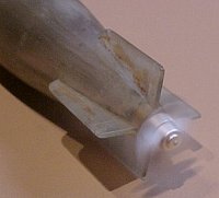
The larger rudders are the horizontal rudders (depth setting)
The smaller rudders are vertical rudders (direction or steering)
Power is derived from burning a mixture of 2800 PSI compressed air with highly volatile alcohol based fuel and water in pre-determined proportions, when ignited a gas is produced which can be likened to steam which operated a steam turbine.
It is said that each of these full size torpedoes were precision made by craftsmen and cost as much to produce as a car, around 10,000 USD!
The majority of the torpedo body was made from a steel alloy, the inside was cadmium plated, the warhead section is not specified as being anything different, however when the magnetic detonators were added later in WW2 the body would need to be of a non magnetic material, possibly bronze as in the German G7 torpedo's. The main body was not painted, they were covered in grease most of their lives anyway, however there was a lot of nose art painted on the warheads of all styles.
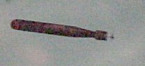
For paint colors I have used Tamiya "Silver" for the main body and a 80/30 mixture of Tamiya "copper" and "bronze" to give a realistic bronzy look.
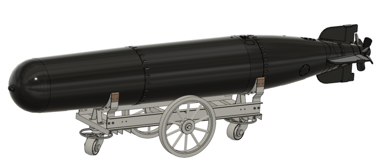
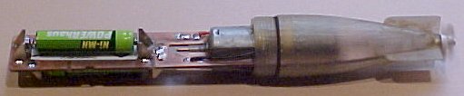
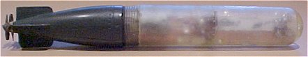
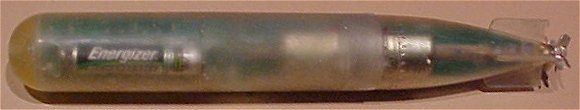
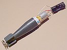
This is a completed Mk13-1 complete with my 3D printed bodies (www.shapeways.com), printed circuit board, brushless motor, ESC and my solid silver propellers.
Here is my latest 2019 corrected drawing of the USN MK13, MK13-1 and MK13-2
I redrew this with the correct dimensions quoted from the US Navy Ordnance Pamphlet 950, Issued July, 1943.
This is the circuit diagram for the new printed circuit board that mounts all the stuff inside the model MK13-1 torpedo and drives the Electronic Speed Controller for it's brushless motor. This circuit can also be used for testing ESC's or servo's or even controlling them for other applications by opening and closing the reed switch. There is a tiny on/off switch to isolate the battery followed by a tiny micro switch that becomes closed once the torpedo's forward body is slid all the way closed and watertight. At this point the ESC will fire up and you will hear all sorts of start up noises coming from the motor, however the magnetic reed switch is still open as the torpedo is not yet in a cradle or torpedo tube and/or near a magnet. Most, if not all, ESC's, for safety reasons, will not start the motor until the servo signal is at minimum or neutral position (1millisecond pulse width) which will happen once a magnet comes close to the reed switch and it, in turn, shorts out the potentiometer. At this point the ESC finds neutral and usually makes a few more noises via the motor and the motor will be stopped if it is not already stopped. The torpedo is now "hot" and will start up the motor when it leaves the magnet, i.e when it falls off the roll off rack or leaves the torpedo tube the propellers will be turning at speed! If the ESC has low battery detect, the torpedo will stop when the battery gets down to the low voltage setting, failing that, you need to catch it and either remove the front body or put a magnet close to the reed switch. The potentiometer allows full speed control from 0 RPM to maximum RPM and the reed switch closing shuts it back down to 0 RPM, or if you use it for servo testing you can set the maximum angle of rotation. I am very pleased with this design and I have built three prototypes of it and it is very repeatable, elegant in operation and really simple to boot!
Once the torpedo is "hot" it is consuming the battery, the most I have seen for an idle ESC is a few milliamps so there is plenty of battery life to have some fun but remember to turn them off after a few hours or you WILL destroy the LIPO batteries.
The brushless motors that I have tried are all 18mm diameter and have KV ratings from 1500 to 2000, at maximum revs they will get hot after 30 seconds running but will lift the torpedo clean out of the water, so some caution is required here. I have put an extra resistor, R3, across the potentiometer to allow for some prudent maximum speed adjustment.
My prototype Mk13-1 weighs in at only 65 grams and floats way too high in the water, The scaled weight (or mass) of the MK13-1 at 1/20th scale is 95.62 grams so I need to add 30 grams to the inside to get the weight correct. I experimented with 4 x 4" (100mm) nails tied on to the outside of the torpedo secured with small cable ties. Then I came up with lead fishing weights, these are available in all manner of shapes and sizes.
Bear in mind that these torpedo's don't come back, so if you point them at a big lake, you need to be able to get to the other side! Depending on the speed setting the batteries will probably run for at least 15 minutes and they can certainly move!
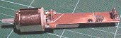
Torpedo model - Circa 2003
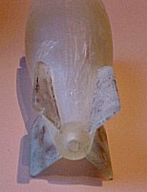
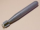
The almost finished resin cast model
The objective is an operational 1/20th scale WW2 US Navy MkXIII Torpedo complete with dual counter-rotational propellers, This is almost complete as the photo's above and below show. I have a completed and relatively easy to make single prop model and it performs well except that the body of the "fish" rotates in the opposite direction to the propeller and that's just not good enough as it makes the torpedo wander, however for launching in a large lake the single prop version is easy to make and fairly cheap so you can afford to lose one or two. This is made from Balsa and Pipe and details are below.
I have been working for some time on a molded resin body torpedo and a printed circuit board, this has been experimental and I didn't really know how to do it all that well but I am giving it my best shot (and I've learned a lot about how not to do it) as lots of people want me to make them torpedo's and it takes forever to make them with pipe and balsa wood.
This is the beginning of the resin torpedo with the polished brass master of the rear section of the torpedo that I made, I tried making wax castings of this to use as the two halves of the outside mold and gave up on that idea after about 20 attempts and four different kinds of release agent, there seemed to be no predictability in the results, so I had a rubber mold made professionally by a jewellery mold maker. I then turned up an inner part on the modelling lathe and after a couple of false starts again with release agents and using different resins and the odd disaster or two I have FINALLY managed to make a successful hollow resin casting, Whoohoo! The rubber mold is smaller than the original brass by a few percent and this is apparently quite normal for that type of natural rubber mold.
The outside finish is actually pretty good, the lines that you can see are from brushing lashings of thick silicon release agent onto the inner brass "dolly" so that I didn't have to chisel it out of the resin yet again! There are a few small air bubbles and a few other slight problems but I am very pleased with the result of many months work.
So that's one made, I wonder if I can make two? Oh and I need to make the front part yet too!
The original thought was that this version would screw together with an "O"ring to keep it dry, didn't work!
And the this torpedo goes too! I have clocked the new resin torpedo at the equivalent to full size 72 Klm per hour (45mph) with two modified 130 Mabuchi motors and two 750mAH AAA NiMH batteries and it goes for more than 15 minutes on a full charge, I had to go and buy a new battery charger so that I could charge the NiMH batteries in a couple of hours as the old charger was taking day's. Sony make a fantastic small charger for two AA or AAA NiMH batteries for about AUD$50 (USD$30)
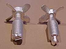
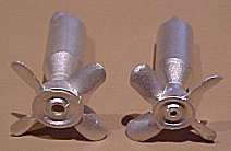
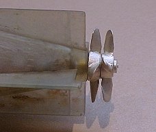
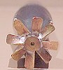
These are the new propellers that I had cast in solid silver (well they don't weigh much even with the casting sprues and it was cheaper than the casting fee to get some cast in brass) and I want to try molding resin props as well in the same mold so I just got a few made to try. As you can see the hubs are tapered to match the shape of the torpedo body so the front prop has a larger hub than the rear and different size holes -2mm and 1mm for the shaft within the shaft. I have made the blades the same size on both props to move the same amount of water to help prevent torpedo body rotation so the rear propeller is smaller in overall diameter by the difference in hub size, from all my photo's this appears to be true of the full size torpedo'ss as well and puzzled me for a while (quite logical when you think about it).
The Full size MkXIII Torpedo was 22.5" diameter (not 21" like the longer torpedo's) and 13'5" long (not 13' 6") - the existing 1/20scale model is 26mm dia and 206mm long. The new one will be 28.5mm diameter and 204.5mm long and so I will need to modify or make new roll off racks to fit the larger diameter. That's one problem with doing research, you mostly find out that you were wrong last time!
The first new front moulding sort of works, the outside is fine but the whole internal thread idea doesn't work, too thin and too hard to make - new idea required here!
![]() THE NEW PCB HAS
ARRIVED Whoohoo (on Mayday - is that ominous!)
THE NEW PCB HAS
ARRIVED Whoohoo (on Mayday - is that ominous!)
By the end of Mayday (1st May, 2003)
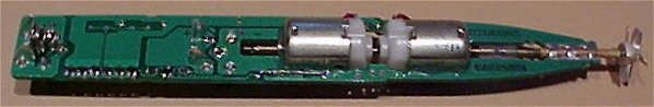
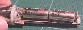
The completed circuit board with it's three "Ultra Low On Resistance" MosFet transistors per motor. It has a couple of tiny issues but no major stuffups!
There is a reed switch, two s.m.t. (surface mount) resistors, three s.m.t. capacitors and seven s.m.t. transistors on this as well as the four battery clips and the two modified (hollow) motors. There's a good name - "hollow motor torpedo's"
A brand new complete "production" torpedo (it's a pity the photo doesn't do it justice but it will look better when it's painted) there are still a couple of issues to fix but it's damn close now. The front molding was made with a silicon rubber outside mold and a brass internal "dolly". I am going to try a silicon inner dolly when I can figure out how to make one as it won't stick to the resin, the brass one is very difficult to remove unless it has a really thick coating of silicon grease on it.
Early Stuff
(It's fairly easy to see the differences in the shape)
The original single prop balsa and pipe 1/20 scale "fish" in operation, don't worry, it doesn't go bang (well not yet anyway!) This is our MarkV.
4 blade Prop Development
(Pre modelling lathe)
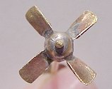
A bit rough yet, but it seems to perform extremely well, I have also made an opposite pitch version for the counter-rotational true scale model. The hub is made from an M4 brass dome nut and the blades from flat sheet. The blades were pre-bent and tightly fitted into saw slots in the hub before soldering into place, then twisting the blades and rough shaping. The dome of the hub will be cut off once I am happy with the performance and the centre thread filled with a brass screw and drilled out to the correct size (once I know what that is).
I am planning on casting these props in Resin or Zinc once they are finished, so let me know how many you want!
I am also experimenting with a two motor model with the shaft of one motor going through the hollow shaft of another, I have knocked out the steel motor spindles (2mm) and replaced them with hollow brass tube (2mm OD 1.5+mm ID), tricky but not difficult!
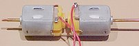
These photo's show the counter rotating props and in operation is looking fabulous! stay tuned for more developments here! This looks like THE plan!
Feb 2001 - This is the experimental 2 prop model with the finished props and a single N size battery (1.5Volt) This is looking really good! new circuit board coming soon with professional battery clips and hopefully we can fit in two batteries. This is the first torpedo housing with the smaller fins, I will be doing another body design because after much research this one's shape is not quite right and the horizontal and vertical fins were actually different.
Shhhhh!!! I also have some miniature switches that I have found for the detonator!
The Original PT-Boat.com - MarkVI - Single Prop
After much experimenting with more refined battery holders, types of batteries, props and so forth, I have settled on the following single prop "production" design. It seems it's very easy to move something slightly and have an unstable sinking torpedo or one that bobs about like a seal. I have made the tail fins larger than scale to mostly stop the body rotation with a single prop.
The Torpedo Factory 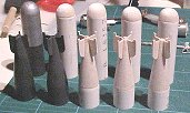
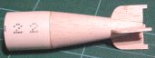
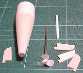 The Tail
section pieces ready for assembly
The Tail
section pieces ready for assembly
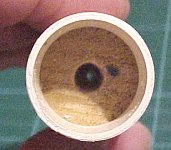
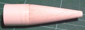
The main body of the Torpedo is made from 25 mm telecom conduit tubing which just happens to tightly fit a Mabuchi 260 motor and the outside diameter is just over 26mm diameter - perfect! Both the front domed end and the tapered tail are made from Balsa which has been turned in a stand drill to fit within the tubing, to drill the prop shaft hole and to achieve the final shape - mostly with sandpaper.
 The Balsa tail
is turned down to fit inside the PVC tubing, glued in and once the glue is dry
the final shape is applied. The tubing is also cut to length in the stand drill
by using a mandrel that fits neatly inside the tubing covered in PTFE plumbing
tape.
The Balsa tail
is turned down to fit inside the PVC tubing, glued in and once the glue is dry
the final shape is applied. The tubing is also cut to length in the stand drill
by using a mandrel that fits neatly inside the tubing covered in PTFE plumbing
tape.
The inside tail section is cored out to allow for the motor end and the silicon rubber coupling from the 2mm motor shaft to the 2mm brass prop shaft.
The outer prop shaft is either thin walled brass tubing or plastic tubing, both seem to work well, brass tubing is probably easier and better but slightly heavier.
The fins are slightly angled on the single prop version to reduce rotation and to straighten the path against the single prop's rotation, pretty difficult to make these go straight though!
The domed front is fitted in a similar way although only the rounded dome itself is balsa with a little step to fit into to tube. You need to make a very accurate dome or it will act to steer the torpedo in different directions as the body rotates with the single prop, makes the things very unpredictable.
I understand now why torpedo's HAD to have two propellers!
The electrics are mounted on home made printed circuit board made from 1/16" double sided PCB fibreglass laminate, available from most hobby shops. The copper sections are isolated by cutting through with a knife and pealing the copper away. The battery clips are made from some terminals from old electrical parts and are surface soldered on the top of the board. (not all that reliable, we have some new battery clips now) holes are drilled in the board for the reed switch wires and they are soldered top and bottom.
The batteries are 1.5V "N" size. The board has been made as small as possible to keep the weight down.
 Slots have
been sawed through the PCB for the motor terminals which slot in and are then
soldered top and bottom. Use a sparing amount of Araldite to glue the motor to
the board and to fill the breather holes at the front and back of the motor to
stop water getting in, also glue the tabs that secure the metal motor body to
the rear in the recesses to prevent the rear of the motor from being pulled off
when seperating the torpedo halves. Some of the cheaper motors have fairly poor
mechanical tolerance and I've found the better quality motors are not much more
expensive and are certainly worth the extra few cents, sometimes the rear
plastic motor end needs to be filed a little down to the same diameter as the
metal jacket.
Slots have
been sawed through the PCB for the motor terminals which slot in and are then
soldered top and bottom. Use a sparing amount of Araldite to glue the motor to
the board and to fill the breather holes at the front and back of the motor to
stop water getting in, also glue the tabs that secure the metal motor body to
the rear in the recesses to prevent the rear of the motor from being pulled off
when seperating the torpedo halves. Some of the cheaper motors have fairly poor
mechanical tolerance and I've found the better quality motors are not much more
expensive and are certainly worth the extra few cents, sometimes the rear
plastic motor end needs to be filed a little down to the same diameter as the
metal jacket.
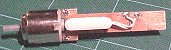
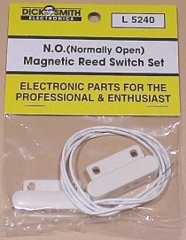 The reed
switch and magnet.
The reed
switch and magnet.
In this type of reed switch the mounting foot can be broken off to reduce the overall weight. The magnet is mounted on the Roll Off Rack and the reed is mounted inside the torpedo, the purpose of the reed switch is to allow the motor to start automatically once the torpedo rolls off the side of the PT-Boat, make sure the magnet is mounted around the right way or it won't work as these are magnet biased to stay ON when away from the main magnet! BEWARE the description, you need a reed that is OPEN when near the magnet!!!!! If you can find just the glass reed switch part you need the ones with one lead at one end (Com) and two leads at the other (NO/NC).
The single prop plans (see above for new 4 blade prop)
Printed Circuit Board Layout
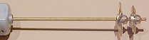
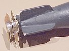
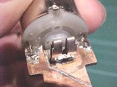
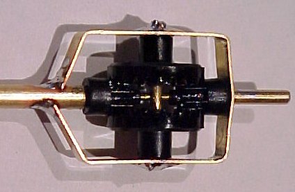
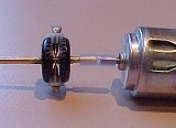
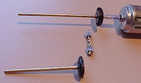
The Counter-Rotating Prop Gearbox
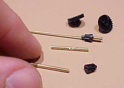
The fabricated parts and gears, they're a bit small!
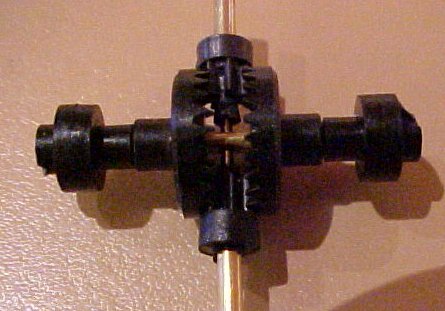
Experimental gearbox, worked well. It also gave me some idea's about using the same gear method to elevate the guns and particularly the operational rocket launchers.
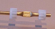
A more refined model but not quite there yet.
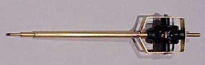
The new simpler 2003 gearbox
I had some new idea's on a simpler gearbox to make a simple twin prop version with a single motor in the new resin body.
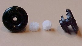
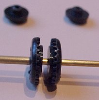
This is built using two each of the "Scalextrix" type slot car (Crown (big) and Pinion (little)) gears, which are a bit bigger than the tiny AFX gears. This means that the inner shaft can be 2mm diameter which is the same as the diameter of the motor shaft and the same size as the shaft on the single prop torpedo. This will fit in the new resin body and with a bit of adjustment to the inside shape to hold the cross beam with the pinion gears this should be fairly quick and easy to make. The crown gears are modified by cutting off the "hat" section with a sharp scalpel and the holes need to be drilled out slightly to fit.
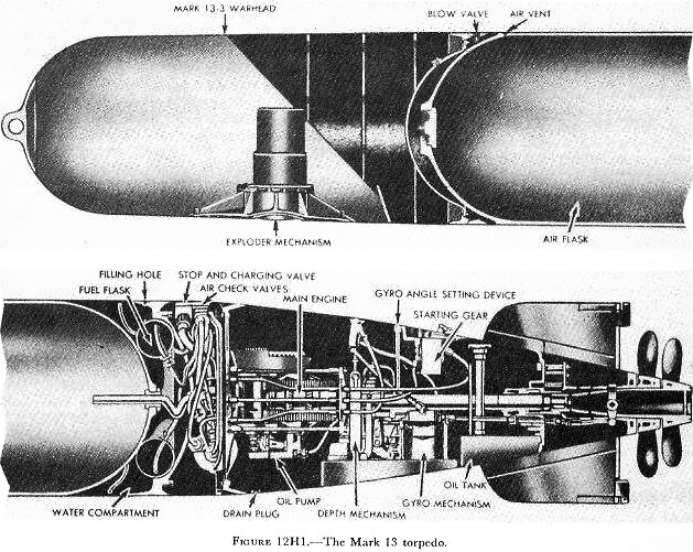
The Original Full Size Mk13 Aircraft Torpedo
The Mark 13 torpedo, compared
with the others, is short and thick: its length is 13 1/2 feet, and its
diameter, 22 1/2 inches. (The others all have the same diameter-21 inches-so
they will fit the standard torpedo tubes.) The Mark 13 is designed for launching
from aircraft and PT boats. Its range is 6,000 yards at an average speed of 33
1/2 knots, and it carries 600 pounds of high explosive.
Mark 14 and 23 types. The Mark 14 torpedo is fired from submarines. Its length
is about 20 1/2 feet. It offers a choice of two speeds. At the high-speed
setting it has a range of 4,500 yards, at an average speed of 46 knots. At the
low-speed setting its range is 9,000 yards, and its average speed is 32 knots.
It carries 600 pounds of high explosive.
The Mark 23 torpedo is exactly like the Mark 14, except that it has no
speed-change mechanism. It operates only at high speed.
Mark 15 type. The Mark 15
torpedo is launched from the deck tubes of surface ships. It is 24 feet long,
and carries an explosive charge of about 800 pounds.
It has three speeds:
26 1/2 knots (range 15,000 yards);
33 1/2 knots (range 10,000 yards);
and 45 knots (range 6,000 yards).
Mark 16 type. The Mark 16 is a �chemical� torpedo. It uses a strong solution
of hydrogen peroxide, rather than compressed air, to support the combustion of
its fuel. This feature gives the Mark 16 a relatively high speed and long range,
and enables it to carry a relatively heavy charge of explosive.
Mark 18 type. The Mark 18 is the only nonhoming electric torpedo now in the
Fleet. Its principal source of energy is a large lead-acid storage battery. It
has a length of about 20 1/2 feet, and an effective range of 4,000 yards at an
average speed of 29 knots.
H. Aircraft
Torpedoes
12H1. Construction and
use
Aircraft torpedoes came into common tactical use during World War II, as
alternate weapons to aircraft bombs for use in attacks on surface ships. Torpedo
attacks, however, ordinarily are not made against well-defended units, unless
supporting attack is made simultaneously by other types of planes to divide the
enemy antiaircraft fire. When properly employed, torpedo attack may force enemy
ships to maneuver into an unfavorable position with respect to a main attack
delivered by own ships, or accept the penalty of torpedo hits.
Aircraft torpedoes must be able to withstand heavy water impacts. They must also
be capable of maintaining stable flight from plane to water, and a stable course
through the water to the target. The Mark 13 torpedo, shown in figure
12H1, is one of the older types still
in service use. It is similar to the Mark 15 torpedo but differs in certain
details of size and design, including the incorporation of special stabilization
elements necessary for effective launching from aircraft.
An aircraft torpedo usually is suspended between two racks, which have
suspension cables running between them and around the torpedo. A small stop
bolt, projecting downward from the plane into a hole in the torpedo casing,
serves to prevent fore-and-aft slipping of the torpedo in its cables. When one
end of each cable is released, the torpedo falls away.
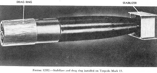
12H2. Mark
l3 torpedo
The Mark 13 torpedo differs from the Mark 15 torpedo in the following ways:
1. The Mark 13 torpedo has better provision for air stabilization, being much
shorter and slightly larger in diameter. It is 13 feet 5 inches long, and 22.42
inches in diameter.
2. The Mark 13 torpedo has greater capacity for withstanding water impact.
3. The Mark 13 torpedo contains a smaller explosive charge: 600 pounds of HBX.
4. The Mark 13 torpedo has a shorter designed range: 5,700 yards.
5. The Mark 13 torpedo has a single speed: 33.5 knots.
6. The Mark 13 torpedo has a water trip delay valve to prevent ignition until
the torpedo enters the water.
7. The Mark 13 torpedo has a shroud ring around its tail vanes, which tends to
minimize hooking and broaching upon water entry, and makes for greater stability
during the water run.
8. The Mark 13 torpedo is rigged for launching with a box-shaped plywood
stabilizer fitted over the fins and shroud ring. This stabilizer causes the
torpedo to fall in a smooth curve, and to enter the water head first. The
stabilizer breaks up on impact with the water. A parachute drogue stabilizer has
been designed as a substitute for the box stabilizer.
9. The Mark 13 torpedo has a drag ring, in the form of a plywood tube open at
each end, fitted over its head. The drag ring slows the torpedo�s rate of
fall, tends to reduce wobbling, and acts as a shock absorber on water impact.
The stabilizer and drag ring are shown in figure
12H2. This drag ring is not used when
the torpedo is rigged with a parachute stabilizer.
Near the after end of the torpedo is a starting lever. When the torpedo is
installed on the plane, a toggle is hooked to this lever and is attached to the
aircraft by a lanyard. When the torpedo is released, action of the lanyard and
toggle trips the starting lever, but a water trip delay valve serves to prevent
the combustion flask from lighting off until water entry. A gyro-locking
mechanism is also provided. When the torpedo is installed on the plane, the gyro
is locked with its axis parallel to the axis of the plane. The gyro begins to
spin on release from the plane. The gyro will therefore keep the torpedo on the
course determined by the direction of aircraft travel at the instant of release.
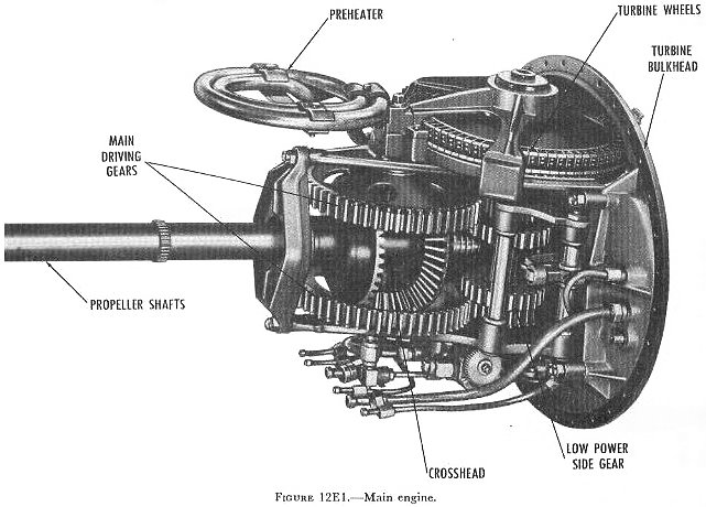
E. Main Engine of a Mark 15 Torpedo
12E1. General
The main engine is located entirely within the afterbody, and is supported by
A-frames secured to the after side of the turbine bulkhead. It consists of the
turbine wheels, gear reduction train, and propeller shafts, along with the
frames, spindles, shafts, and bearings that support these parts, and the oiling
system that lubricates them. The main engine of a Mark 15 torpedo, viewed from
the starboard side, is shown in figure
12E1.
12E2.
Functional description
The main engine converts turbine-wheel rotation into propeller rotation. In
order to do this effectively, it must have several special features.
Because of the high velocity at which the combustion gases strike the turbines,
the turbine wheels must turn at high speed in order to use the available energy
efficiently. But, if the propellers are to operate efficiently, they must turn
more slowly than the turbine wheels, and develop a higher torque. The main
engine must therefore include a gear reduction train.
The torpedo is provided with two propellers, which rotate in opposite directions
but at the same speed. This feature is necessary because the torque developed by
a single propeller would tend to roll the torpedo in the opposite direction. As
previously stated, the two turbine wheels also turn in opposite directions. But
it is not possible to drive each propeller with a different turbine wheel,
because the first turbine wheel develops a much higher torque than the second.
The main engine must therefore combine the two unequal torques developed by the
turbine wheels, and then divide this force equally between the two
counter-rotating propellers.
Finally, the main engine must continuously lubricate its moving parts throughout
the torpedo run.
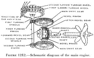
12E3. Gear
train
Figure 12E2
is a schematic diagram of the main engine. This illustration should be compared
with figure 12E1,
bearing in mind that the two views are from opposite sides. (The side gears are
not shown in figure 12E2;
they will be described later.)
Each of the two turbine wheels is mounted on a separate spindle. The first
turbine spindle is short and hollow, and carries the first turbine pinion at its
lower end. The second turbine spindle is longer, and passes through the opening
in the first spindle. The second turbine pinion is mounted at the bottom of the
second turbine spindle.
As they pass through the
nozzles, the hot combustion gases expand and reach a high speed-about 4,000 feet
per second. They strike the blades of the first (lower) turbine wheel, and spin
it counterclockwise (as viewed from the top of the torpedo). The first turbine
turns its spindle, and the first turbine pinion, counterclockwise. The pinion
meshes with the upper main drive gear, and turns it clockwise. The drive gear
turns the upper bevel pinion clockwise.
The combustion gases are deflected from the blades of the first turbine, and
strike the blades of the second (upper) turbine. The second turbine spins
clockwise (still looking down from the top). The second turbine turns the second
turbine spindle, and the second turbine pinion. The second turbine pinion turns
the lower main drive gear counterclockwise.
Each of the 2 bevel pinions meshes with both bevel gears. Working together, the
2 pinions turn the 2 bevel gears. The forward bevel gear turns counterclockwise
(looking aft from the forward end of the engine). The after bevel gear turns the
forward (outer) propeller shaft, which turns the forward propeller. The forward
propeller shaft is hollow; the after propeller shaft turns inside it. The
forward bevel gear turns the after (inner) propeller shaft, which turns the
after propeller. Because the two propeller shafts are linked together through
the bevel gears and bevel pinions, they turn in opposite directions at the same
speed.
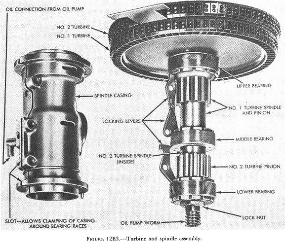
12E4. Turbines and
turbine spindles
Figure 12E3
shows the turbine and spindle assembly; the spindle casing is at the left. In
both turbines, the blades are of crescent-shaped cross section. On the end of
each blade is a small projection to which the turbine band is riveted. The
turbine band is made up of overlapping segments. The clearance at the butt ends
of the segments gives them room to expand when they get hot. The blades of the
second turbine curve in the opposite direction from those of the first turbine.
And the blades of the second turbine are slightly larger than those of the
first, so that the gases can keep expanding as they pass through the turbine.
The upper and middle bearings support the first turbine spindle. The second
turbine spindle, which passes through the first, is supported by the lower
bearing and the top bearing. (The top bearing does not show in figure
12E3; it is located above the second
turbine wheel.)
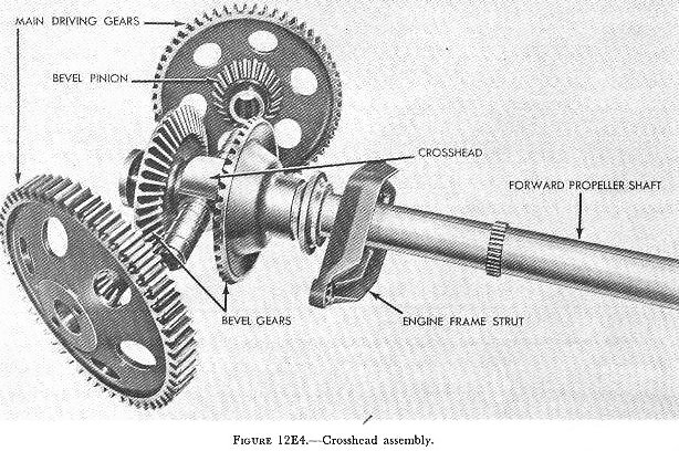
12E5.
Crosshead assembly
The crosshead is shown in figure 12E4.
Its outer ends are supported in the two A-frames. Bronze bushings fit over the
two crosshead shafts. These bushings serve as bearings for the main drive gears
and bevel pinions. (Each drive gear and pinion combination is machined from a
single forging.) In figure 12E4 the bushings are in place on the crosshead. Note
the spiral oil grooves on the surface of the bushings. Notice also, to the right
of the strut, a small pinion gear machined on the outside of the forward
propeller shaft. This pinion supplies the power that drives the steering
mechanism.
The after propeller shaft passes through the cross-head in a floating bronze
bushing. The forward bevel gear is keyed to the after (inner) propeller shaft;
the after bevel gear is keyed to the forward (outer) propeller shaft. The outer
propeller shaft turns in a bearing in the engine frame strut. This bearing
supports the shaft radially; it prevents any motion at right angles to the
torpedo axis. Between the after bevel gear and the crosshead are a bearing
washer and a thrust bearing.
12E6. Engine thrust
As the propellers turn, they develop a thrust, or pushing force. They transmit
this thrust to their shafts. To drive the torpedo through the water, this thrust
must be taken from the propeller shafts and applied to the shell of the torpedo.
This is done in three ways:
The after bevel gear is driven by the two bevel pinions. Because of the slope of
the gear teeth, the turning force of the bevel pinions tends to push the bevel
gear aft. But the thrust of the forward propeller tends to push the bevel gear
forward. The thrust of the propeller is stronger than that of the gears. A part
of the thrust of the forward propeller therefore goes through the after bevel
gear to the bevel pinions, and from there to the crosshead. The rest of the
thrust from the forward propeller is applied to the crosshead directly, through
a thrust bearing and washer.
The crosshead transmits the forward thrust through the A-frames and the turbine
bulkhead to the shell of the torpedo. The after propeller shaft applies its
thrust to a thrust bearing mounted on the after side of the turbine spindle
casing. The spindle casing carries the thrust through the A-frames to the
turbine bulkhead.
12E7. Engine balancing
Any rapidly rotating body develops a gyroscopic action, and resists any force
that tends to turn its axis of rotation. The engine parts of a Mark 15 torpedo
rotate fast enough to develop a considerable gyroscopic action. To keep this
action from interfering with the steering mechanism of the torpedo, the main
engine is balanced. The gyroscopic force of each of the principal rotating parts
is balanced by the force of a similar part rotating in the opposite direction.
For example, the gyro action of the first turbine wheel is balanced by that of
the second. Other pairs of counter-rotating parts include the turbine pinions,
the main drive gears, the bevel pinions, and the bevel gears.
12E10. Exhaust system
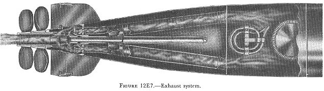
Figure 12E7
shows the exhaust system of a Mark 15 torpedo, looking down from the top. The
two tubes
carry exhaust gases from the space above the turbines to the tail section. Near
the after end of the afterbody, each tube separates into two branches. (In figure
12E7, the lower branch of each tube is
hidden.) The exhaust gases enter the tail section through four openings in the
after bulkhead of the afterbody.
When the torpedo is under way, the main engine space is filled with a fog of
oil. If this fog is allowed to mix with the hot exhaust gases it will burn. The
torpedo will then leave a heavy wake of smoke. This is prevented in two ways:
1. Under the turbines, attached to the top engine frame, is a sheet steel pan
called the turbine oil guard. This pan, together with thin horizontal and
vertical bulkheads, keeps oil fog out of the exhaust system.
2. Above the upper turbine spindle bearing is a baffle, called the oil deflector
ring. This ring keeps the oil in the spindle bearing from entering the turbine
exhaust space.