German S-100 Class Schnellboot (Fast Boat)
The SBoot Electrics
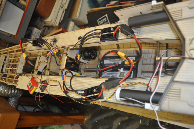
There is a smattering of electrics in this boat so far and I'm not finished yet, three batteries, three speed controllers feeding three brushless motors, three rudder servos, the torpedo door servo and a device to slow it down, my three way buffer to drive the three speed controllers, I will be adding a controller for the deck lights and to fire the torpedo's and potentially the big canon.
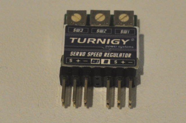
This little device acts to slow down the signal from the receiver to one or more servos, I use this on the torpedo door servo to slow it right down. the original boat torpedo doors were opened by a wheel operated by the torpedoman.
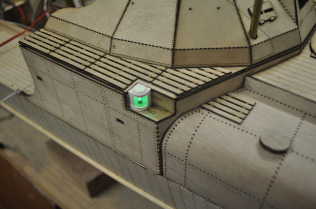
The starboard green light.
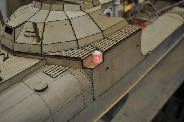
The port red light
I recently (2015) bought three 120Amp waterproof brushless speed controls, however I bought three different Turnigy 120 Amp controllers as I was not happy with what I had as they didn't play too well together.
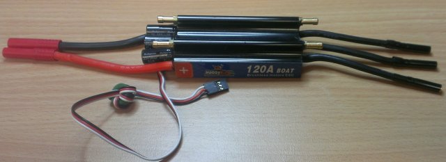
These seem to work OK and have reverse which starts from about mid stick position, however they don't seem all that smooth at the low end of the revs but we'll wait and see if that is an issue or not. Having the same amount of reverse as forward is not a good idea in a boat as it will "dig in" going backwards and swamp the boat, even in a car you only have 1 reverse gear, I'd prefer to have more forward stick and a smoother start with only about 10% reverse speed but getting a speed controller with reverse at all seems to be a bit of a trick so lets not be too choosy.
I also tried one of these speed controllers on the 1/35th Schnellboot model with three much smaller brushless motors all wired in parallel to see how that works, could have been a disastrously short trip as I wasn't sure what the speed controller would make of the signal back from all three motors but as long as the motors can run freely they seem to sink up ok and all run at the same speed and quite controllable so this is the path I will take for the 35th scale models, i.e. one battery, one speed controller. The 35th scale props for the Schnellboot that I bought from G-Force have counter rotating wing propellers so one motor needs to be running in a reverse direction to the other two, to achieve this, two wires of the reversed motor need to be swapped over.
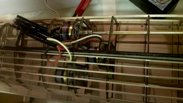
This is the 35th scale Schnellboot hullframe with three small AXI brushless motors installed all wired in parallel running on one 120Amp HobbyKing brushless speed controller. So now when I come to put the three speed controllers in the 20th scale boat, one of the speed controllers doesn't seem to work properly and I don't know if it's the same one that I tried this experiment with?
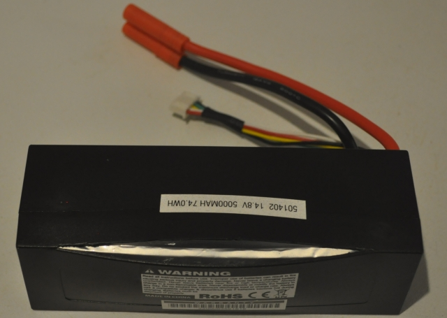
I bought four of these Turnigy 5,000mAH Lipo batteries a few years ago and made sure they were kept charged, these have only been used for the odd experiment so far but two of them have expanded and split.
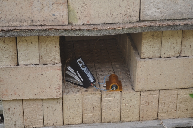
So being the electronics engineer and the mad experimenter I decided to see what happens when they are discharged by a big fat 200 Watt, 1 Ohm resistor, so 15Volts equals 15 Amps, not a huge current I thought! Anyway look what happened! I did this in the safety of my brick bunker with the hose on standby just in case. The question is "Is the battery relatively safe now that it's discharged fully"? Certainly there is no electrical energy in there. How do I dispose of them safely? How do we dispose of camera, phone, laptop Lipo batteries, these have Lithium in them which is very toxic, especially to fish and groundwater.
I thought I may go back to NiMH batteries, having spent many thousands of hours building the boat, do we really want it to catch on fire in a spectacular way?
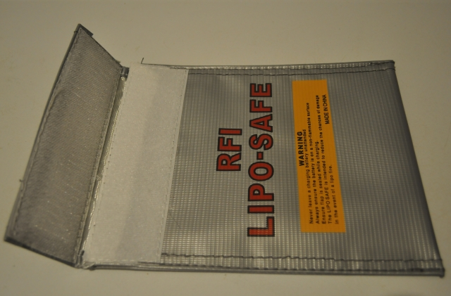
Make sure you have one or more of these fire resistant bags to charge your Lipo batteries in, they are not expensive and your life may well depend on it, This one has a velcro tab that closes over the wires easily. Charge your batteries somewhere safe. There are plenty of examples on the Internet of what happens to Lithium based batteries when they catch fire and explode and it's not pretty.
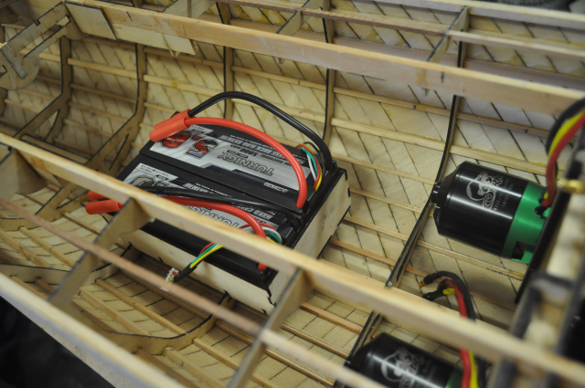
These are the two remaining 5000 mAH Turnigy batteries in the forward battery box, which is mounted under the bridge housing.
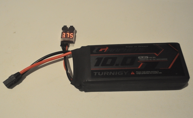
Before the above split 5,000mAH batteries were noticed I had purchased another Turnigy (Graphene 10,000 mAH 4S) battery for the mid motor so that I can get good operating times, I did plan on buying two more of these but I shall play the waiting game now and see how it survives first because I am not happy Mr Turnigy. You can see a cell voltage siren fitted to this battery, this is a safety device that plugs into the balance charging socket and sequentially monitors each cell, there are settable voltage points that operate a loud siren if any of the cells fall below the set point, so this can live in the boat and let us know if the battery is getting low or if something worse starts happening. This is from Radient - www.radientrc.com - it is model RDNA0326 and I bought it from a local hobby shop for about $15.
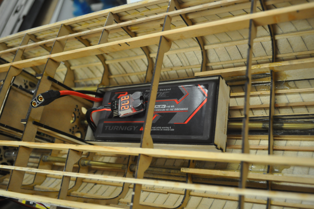
This is the main aft battery box for the 10,000 mAH battery. I built this with a number of notches on the bottom so it locks into the ribs but it can be moved backwards and forward for weight balancing, so I won't glue the battery box in until I have had the boat in the water.
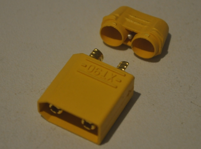
This is a photo of an XT90 male connector to be fitted to my speed controllers, there was an XT90 female connector fitted to the 10,000 mAH Turnigy battery, these are the best connectors that I have found thus far and I will change all of my batteries and speed controllers to this type. You need to remember to put the back cover over the wires first before soldering them on though! These are the easiest connectors to solder onto heavy wires and they are rated at 90Amps plus with a 5mm diameter socket. There is also an XT60 connector which is smaller and lower current rating (60 Amps).
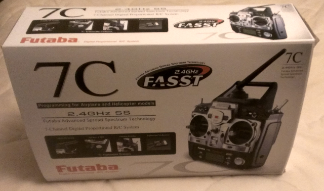
I have purchased a 2.4Ghz Futaba 7 Channel radio system:
This is awesome, I can use all 7 channels to control various functions! One paddle (and one hand) could control both steering and speed so the other paddle can be used for gun altitude / azimuth or similar and there is another rotary knob to proportionally control a servo which I will use to experiment with the "Llurrsen" effect, this then leaves two toggle switches to turn things on/off or launch torpedo's or similar. So five proportional controls and two switches.
I also bought a Venom balance charger:
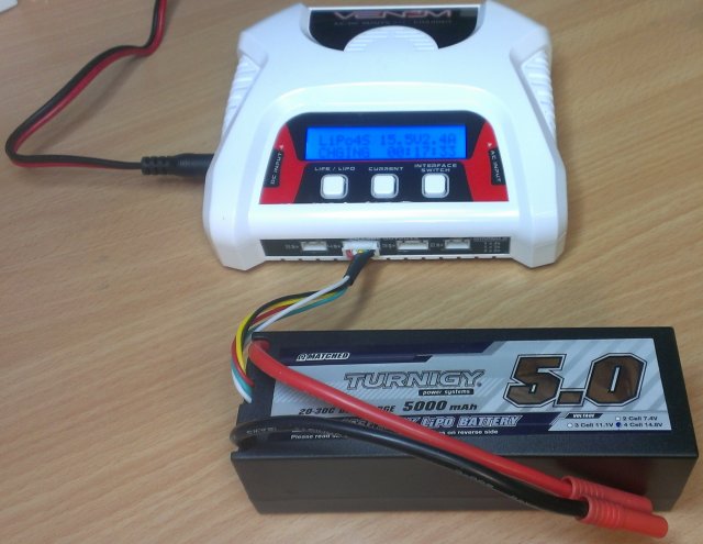
I've had these Turnigy 5,000 mAh 4S batteries for well over a year and had no effective way to balance charge them until I bought the Venom charger in early 2016 and I was surprised how well the batteries have kept their charge.
Balance charging is so important for Lithium batteries as all of the cells are in series and if they are not balanced (in voltage and therefore charge level) one cell can become discharged before the others, especially at high loads (and I am planning very high load currents) and then that cell may reverse polarity with disastrous results.
SPEED CONTROLLER ISSUES
I got the Schnellboot up to the stage of having three motors, prop shafts and props fitted, also three batteries and speed controllers, however all attempts to make them work happily together from the same throttle signal failed, Looking on the Internet revealed a heap of issues with these controllers all of which I had seen first hand, so I had to set it up on the bench and looked at the servo signals. The Hobby King speed controllers when powered up detect the battery voltage and put out a beep via the connected motor for each battery cell (so four beeps for me) followed by a ready signal, beep beep, during this process the speed controllers work out the neutral throttle position between forwards and reverse. However as we cannot plug all the batteries in at exactly the same time the initiation process doesn't work properly, one or two controllers may fire up correctly but not all three of them and then they seemed to do stupid things when the throttle was moved, including one or two motors running flat out.
These speed controllers are programmable through the servo cable to set operating modes, so it is likely that they can be reprogrammed into funny modes by wierd and ficticious signals created while connecting them up. Well that's my theory anyway, I'd love to discuss it with the original design engineer, they may have even allowed for processor software updates to be done this way!
I can't take the boat down to the lake with this level of unreliability, it'll end up sailing off into the sunset! I didn't have any issues with Hull 2 like this with the Castle Creations "Barracuda" 80 Amp controllers, although I did blow one of those up when I connected one of the Turnigy 5,000 mAh LiPo batteries to it and I've only just figured out why - the manual says, don't use the BEC function on a 4 cell LiPo battery pack - or at least it says "use it at entirely your own risk"! I would have bought more of the Barracuda's but Castle Creations don't seem to make them anymore.
Each of the three Hobby King 120A speed controllers has a 4 Amp Battery Eliminator Circuit (BEC) and we don't have enough information to know what would happen if we were to connect them all together and we can only plug in one battery at a time, so we need to disconnect at least two or all three of them, so to save any confusion I disconnected all of them and ran the receiver from a separate receiver battery pack.
I finally decided, after much messing about, that one of the speed controllers was possibly faulty, so I ordered another one, exactly the same, from Hobby King and waited for it to arrive. The new speed controller arrives and I solder on the XT90 battery connector and the motor bullet connectors and put heat shrink tubing over the motor connectors, eagerly plug it in to the boat and ---- it's doing exactly the same thing as the suspect one? I tried swapping motors, batteries, location etc but nothing helped.
Setting the system up on the bench with the oscilloscope connected to the receiver signal revealed that the receiver signal from the Futaba receiver is only about 3 Volts with no load and when connected to a speedcontroller, that isn't powered up and connected to it's main battery, the signal drops to only around 1.5 Volts. I have been down this path before with my brushed motor speed controller!
So I decided to build a signal buffer to boost the receiver signal and to buffer and isolate the outputs separately to each speed controller so that it doesn't matter whether only one, or two, or any of the main batteries are connected or not.
With the buffer in circuit the speed controllers become quite well behaved but I still have an issue with two of the four controllers not going into reverse properly. For the most reliable result I have found that the main batteries need to be connected first, then turn on the transmitter and then the receiver, this seems to give repeatability.
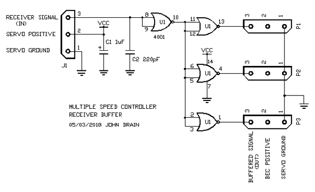
The circuit for the buffer, I added a couple of capacitors to the first draft, a bypass capacitor for stability and a small capacitor on the input to get rid of any stray high frequencies that may be induced into the servo cable from the receiver. I used a 74HCT02 mainly because I had some and also because the inputs are TTL levels so they switch between 0.8V and 1.2V so it can easily handle the 3V output from the Futaba receiver and with a good noise margin.

This is the triple buffer, just one 74HCT02 IC and a couple of leads with plugs. (note no capacitors on this photo)
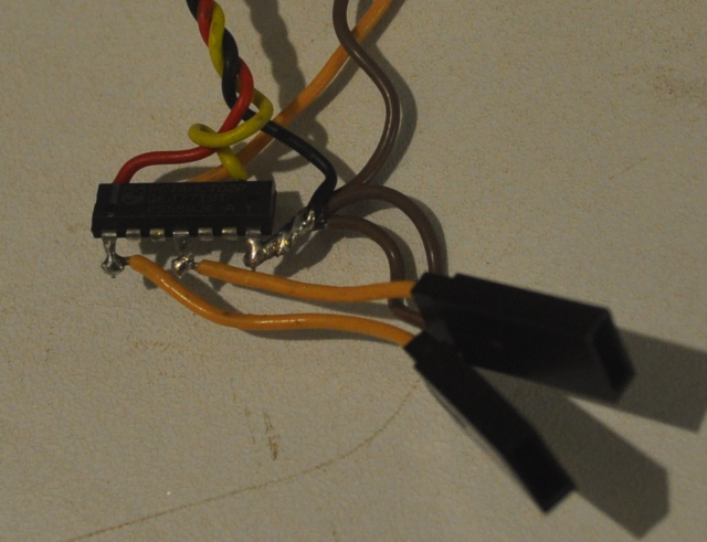
The circuit from the other side. OK it's a bit rough and flimsy but it certainly works, so I dipped the whole thing in a small plastic bottle lid filled with araldite epoxy, with the connectors outside, so that it won't fall apart and it's tough and waterproof.
A Further Issue!
When the Futaba receiver loses signal from the transmitter it continues putting out a valid servo signal on each channel - this is NOT what radio's used to do - so imagine a scenario where the boat is going at full throttle and loses signal from the transmitter - or worse, the transmitter battery goes flat - the boat sails off into the sunset again!
I can see that this "feature" probably has some benefits and has probably been added so that a heli or plane or drone will keep flying if the signal is, say, blocked by a building or a tree or something like that, because at 2.4 GHz radio signals travel more like light and can be easily blocked, but if the signal doesn't come back the flying machine just keeps going until it crashes or runs out of battery and crashes, ultimately unless it has some other sort of clever flight controller it crashes!
So what to do about this new millenium "feature", the Futaba receiver has an LED on it that changes from green to red when the signal fails, I could possibly tap into the red LED drive signal and turn off my buffer by connecting it to the 74HCT02 IC pin 9 or maybe better to pins 12, 5 and 3, then the speed controllers will shut the motors off after a second or so. Hmm the more smarts we put into these things the less smart they become and nobody can understand what the heck is going on!
Note: 2024 The Futaba receiver is programmable to decide what to do if signal is lost!