VeeDrive Gearbox
The modelling objective here is to make an operational 1/20th scale Vee Drive gearbox that looks like the original to allow the PT Boats model V12 engines to be located in their original engine room positions.
In many of the different types of PT Boat and certainly in the Elco 80' boat the center engine faced aft and drove the center prop shaft directly but the port and starboard wing engines faced forward and needed an angled Veedrive gearbox to then drive the wing propshafts back down under these engines. The reason for this was to set the center of gravity of the boat further back and to compress the engine room into a smaller space, this allowed very large fuel tanks to be closer to the centre of the boat.
(It seems that Elco Boats after PT612 may have had all three engines facing aft and no Vee-Drive gearbox, there is some evidence for this in photo's showing the engine room configured this way and the fact that the rear torpedo's were moved much further aft, as well as a photo showing the propellers much further apart than earlier boats.)
NOTE: that even with the VeeDrive gearbox all three propellers turned the same way, clockwise looking from aft.
Wing Engine, Universal Joint Coupling, Vee Drive Gearbox and Propshaft - side top and rear views. I have drawn the mounting flange angle in line with the engine mounting line which is my best educated guess from the original gearbox photo's below and thinking about how you would line up the shafts but this may not be correct, it could have been in line with the propshaft which would make more sense to me for alignment but it doesn't appear to be, or it could be at the centre line between the two shaft angles (half the total angle and like the model will be) although my thinking say's this presents the worst scenario for lining it up in situ.
Rear (engine / prop / aft side) view - The shafts may have been hollow either to allow for alignment to the other shafts or just to reduce the weight. The fact that there is a universal joint on the engine shaft tells me that the gearbox must be primarily lined up with the propshaft and it may be that the hole in the gearbox shafts are 2" diameter the same as the propshaft so that the propshaft or a long 2" rod can be inserted up the propshaft and into the VeeDrive bottom shaft hole to line it up precisely.
Internal detail view - shaft angle difference is 12 degrees, number of gear teeth - approximately 30
The start of the model gearbox, this varies from the original as it will be symmetrical side to side and top to bottom so that I only need to make one half, so the mounting flange follows the center line between the shafts which may be correct but if not it will not be noticeable once installed anyway.
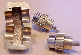
Side View - The round sections and the 4 ball bearings (3mm ID, 10mm OD, 4mm thick) and shafts are from 2 Intel Xeon CPU Fans which were filed down to make the flats that produce the correct angle of 12 degrees. Half of the centre bearing tube section has been filed away to fit the gears and the side of the tube section away from the mounting flange has to be cut off down the centre line of the two shafts so that the bearing mounts are a C section instead of a complete circle. I didn't do this until the rest was completely finished as I didn't want to risk misalignment of the front and back bearing positions on either tube.
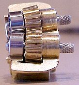
The almost finished master half shell and gears, I have added a bit of a flange at the top and bottom and cut the bearing tubes in half. I hand made these gears from some straight cut gears that I had, fiddly job but they came out OK after many hours. The gear hubs just happened to be 8mm diameter, the same as the ball bearings, so they fit perfectly into the half shell for fit purposes, I can't leave them like that because of wear so I will cut them off and replace with two more ball bearings. Also the gear shaft holes are 3.125mm (1/8") and the gears are 3mm ID so I'll have to do something about that.
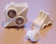
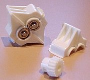
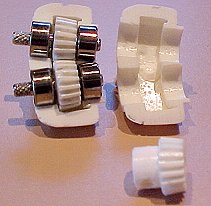
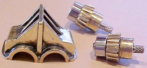
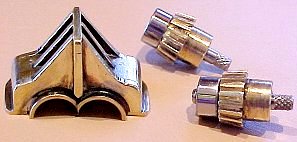
Whoohoo! Silicone RTV mold made and several pours later I have three half shells and I have made a complete gearbox!
I molded the gears in the same mold at the same time not expecting them to work but they both came out really well so I have super glued them onto the shafts just to try out the final gearing idea. The polyester casting material probably won't last long as a gear tooth but I'll give it a try. I can get the gears cast in metal but I will get 5% shrinkage or so and that may make them too small. I used Polytek very low viscosity "Easy Flow 60" polyester resin for these parts - www.polytek.com - great detail, magic to use and de-moldable in half an hour!
HISTORICAL Photo's
Photo's purchased from the PT Boat Museum - http://www.ptboats.org
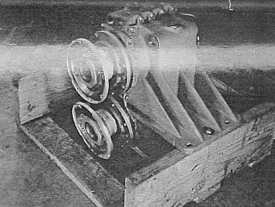
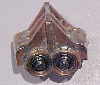
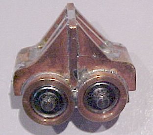
This photo shows the original complete gearbox.
There may have been a number of manufacturers but it seems these were made by Watson and Flagg in New Jersey.
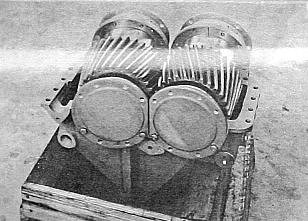
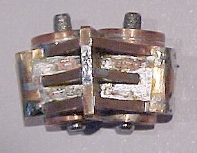
This shows the box with one half of the outer casing removed. Note all the pipe fitting holes front and back.
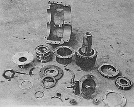
It seems there were two or three front ball bearings and one rear ball bearing. From all the cast in pipe ports on the outer jacket and from other drawings of the engine room layout it seems that the internal gear chamber and the bearings were oil fed and there seems to be a water jacket at least at the top and/or bottom for cooling water and I guess at 1500 BHP it may have got quite warm!
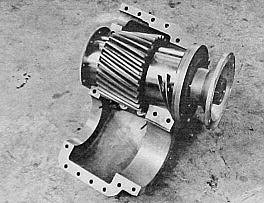
It's quite a complex helical angled gear for it's time, the model gears will be straight cut.
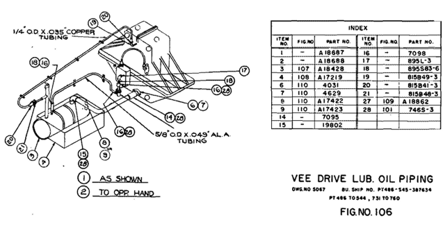
I recently found a spare parts drawing of the oil piping for the Vee Drive gearbox - 2018, this answers a few of my questions.