German S-100 Class Schnellboot (Fast Boat)
The SBoot Kallotte (Skullcap Bridge)
The Kallotte, or Skullcap bridge is a very complicated construction and it had stalled and had me puzzled since I built the complicated and fragile cardboard version many years ago, puzzled about how to make it easy enough for many people to construct, sure I could put together a whole heap of little shaped pieces and hope you could get them all at the required angles and in line but that's not me, I am essentially a manufacturing engineer so making things makeable is what I have always done.

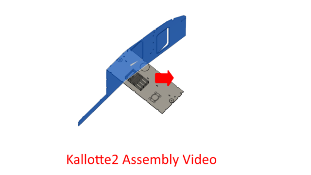
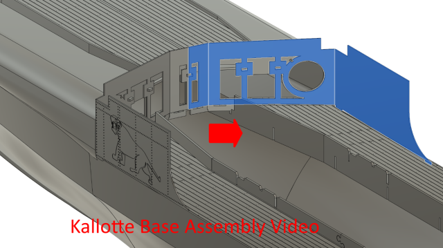
The 3D animated assembly guide for the Kallotte.
The torpedo director added inside the bridge, it needs the binocular part on the top yet?
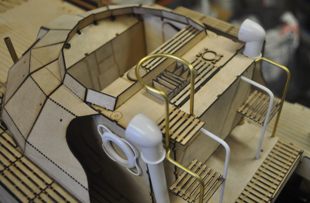
The Kallotte with the top lookout support rail added.
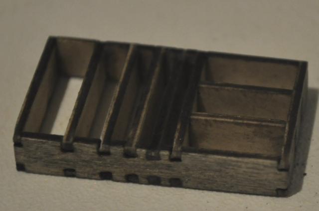
The torpedo director base made up.
I need to find some turn handles for this.
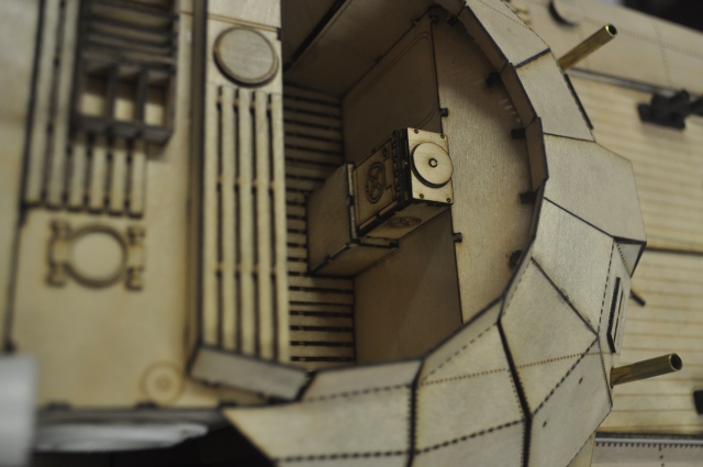
This is where the control column fits within the bridge.
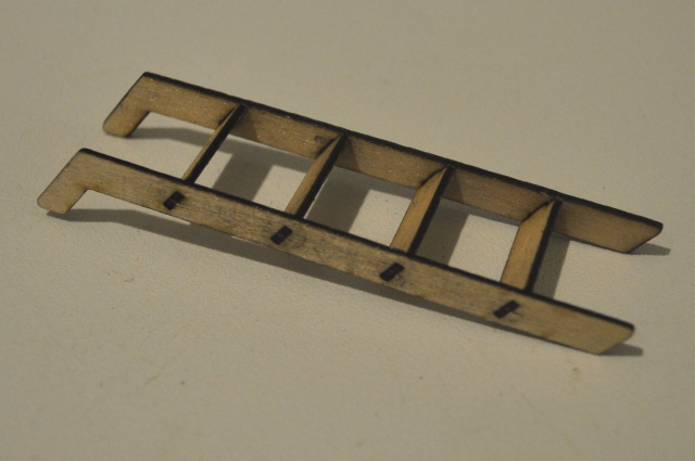
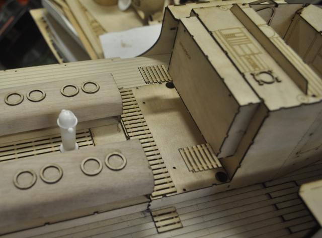
On each side of the Kallotte, behind the torpedo tube, is a ladder to allow access to the foredeck.
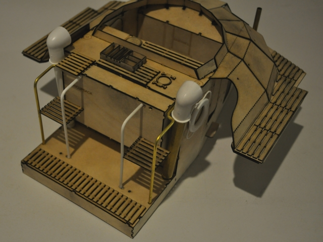
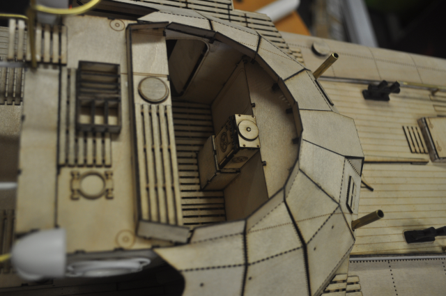
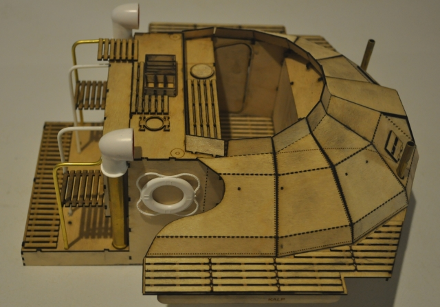
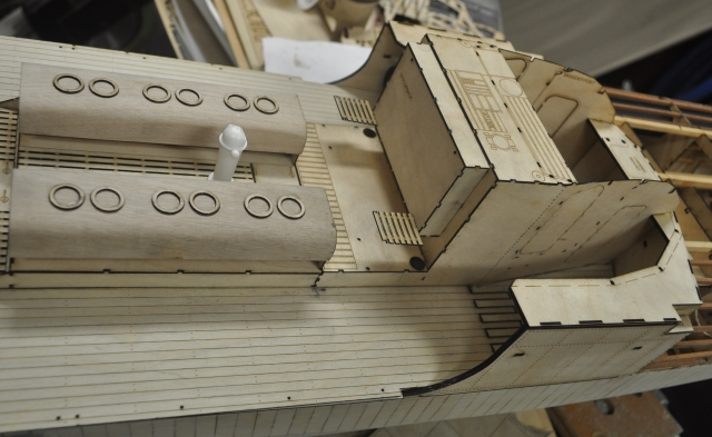
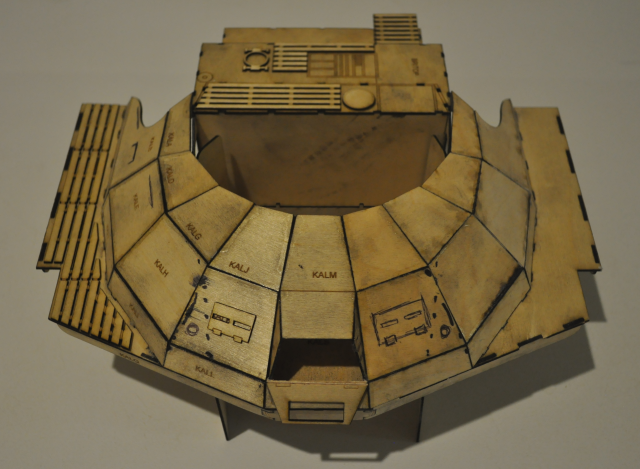
A complete rebuild from a newly cut kit, this view above shows the newly added rear raised deck and climbing platforms, I still messed a few things up with this such as a few holes in the wrong place but hey that's easily fixed, getting all the proportions right is the hard part, I have added the ladders and hand rails and the air vents and a couple of life bouys and built the flare box on top. I still need to do a railing around the upper duckboard at the port side lookout position. I have done one air vent pipe in brass and one in plastic (and yes they are supposed to be splayed outwards at the top), likewise the hand rails are a mixture of plastic and brass, just to show that it can be done in different ways. There is no right way and the Schnellboots were a little like the US boats, they were all a little bit different so there is no such thing as wrong!
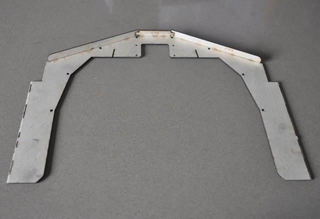
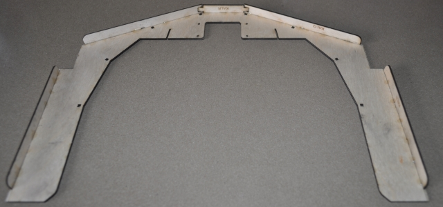
The Kallotte sub frame from the starboard side, I have added a cracker line down the side where the wheelhouse side angle changes, this is much better than trying to join two pieces end to end.
This view shows the aft decking loosley in place and the rear "cupboard" with hanging duckboard platforms in place, I ended up moving these platforms higher and in fact I have lifted the bottom of the "cupboard" up as well in the kit as it didn't look right, the platforms were too low and these definately were at the bottom of the "cupboard", I measured them up from the main deck instead of from the raised deck. Some of these things don't become obvious until the unit is built.
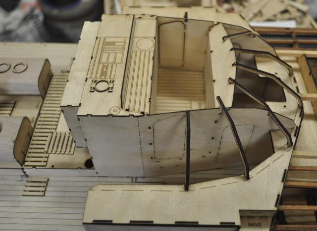
The Kallotte from the starboard side.
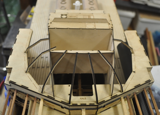
Another view from the rear.
Starting to put the panels on the frame. Start in the middle at the front.
Then add a piece at a time, this angle cracking idea works a treat!
Starting to come together and looking good!
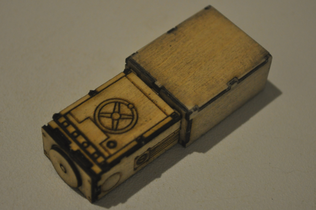
The underside of the plug in section.
All the plug ins in place.
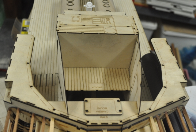
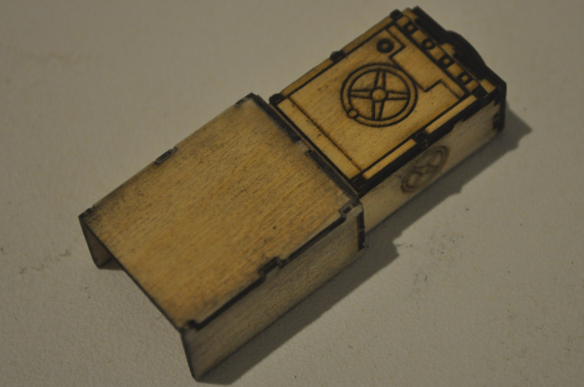
I have added a small camera mount which can be screwed in place from under the Kallotte.
The flare box which sits on top of the Bridge.
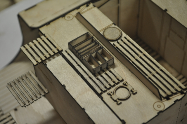
The flare box in place.
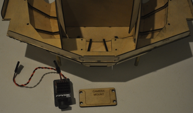
The camera mount and the camera and where it will mount.
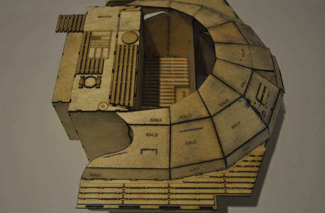
Below are the beginnings of the Kallotte, I had trouble with this from the very beginning, some 12 years ago, around 2005 and it became the stumbling block for the entire project, there was very little information available at that time, virtually no photo's and it didn't make a lot of sense to me. I have spent a number of months working on the latest design and I am very happy with the result so far, there are still a few little issues to sort out but the task is all but complete.
This is a ply version of the original Kallotte design that I did some years ago, which I put together to remember how hard it was to make and hopefully give me some inspiration!
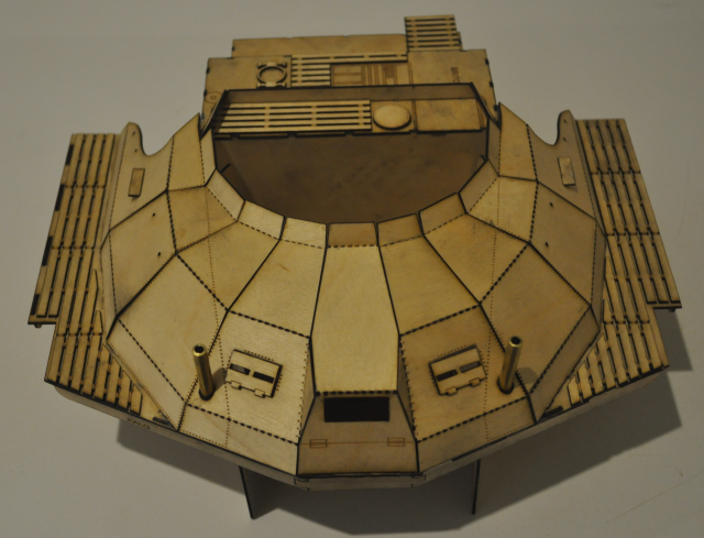
This is a newer version, without all the finger joints between the panels which would be relatively impossible to finish off but not having them makes the construction more difficult. there are also a few new parts such as the duck boards and much more detail designed for the rear section. I made up some frames below the segmented panels to hold them all in the correct angles.
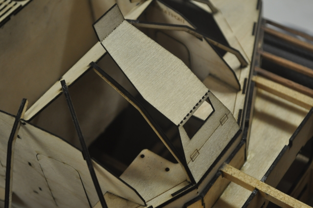
Here you can see the duck boards better and the ones on the floor of the bridge and one of the four doors into the bridge area and the wheelhouse (steuerhaus) in front of it.
This is a view from below showing a couple of the new frames and doors.
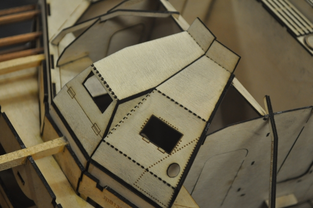
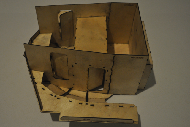
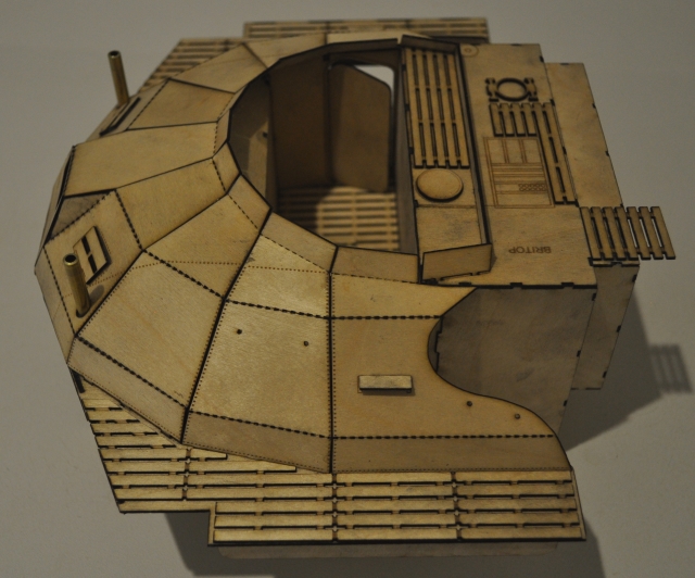
I came up with another idea where I can cut the entire vertical section from one piece of ply by cutting small slots across and then partly breaking it to create a fold, this is magic and and allows the assembly to be much, much simpler. You can also see that I have added laser etched rivets in a number of areas, the side sections of the Kalotte were of aluminium rivetted construction whereas the front section over the wheelhouse was of welded steel.
I am pleased with progress on this part of the project, I can see an easy to make Kallotte now.
A Later Incarnation: January 2018
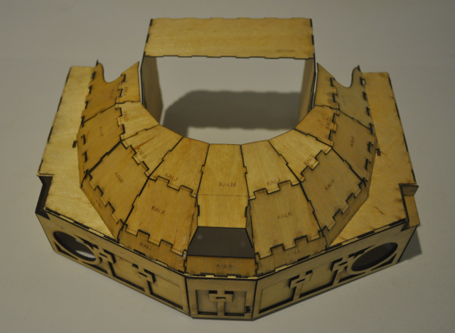
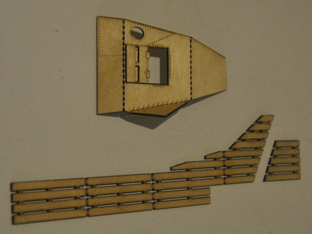
I was inspired by my folding vertical panel idea so I broke off all the individual panels and cleaned up all the frames and laser cut a new set of vertical folding panels complete with the upper most sections. I need to figure out how to make the clear windows that go above these top sections yet and what to make them out of, acryllic cuts really well. I was amazed how strong the structure frame actually is, I expected to break it because the Locktite superglue that I use holds on really well, the ply comes apart before the glue lets go but it survived without any damage at all!

I have made the duck boards a plank wider on this side as a trial, to cover the slots where the "plug" is. The "plug" literally plugs into the middle layer of the three layers of the front and side walls below it, so that the entire Kallotte can be removed at will, I plan to have the torpedo launching system in the rear part of the Kallotte, so that the CO2 cannister can be easily attached/replaced.
This part of the project is virtually finished now, I need to do a few small tweaks to the panels and add a rear raised deck section and a few more detail pieces but I am very pleased and have finally overcome a huge stumbling block in the overall boat kit design. I may actually try making the entire panelled section out of one big interconnected piece, not sure if that will work but well worth a try.
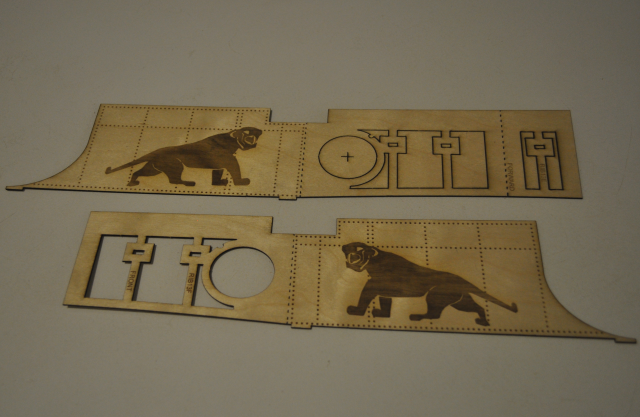
I drew up the Panther, which was portrayed on a number of S Boots, I was hoping that the rivet detail would be superimposed over the Panther etch but alas, because it is raster etched it is all combined by the laser, I would need to produce a separate page with just the rivets where the Panthers are and re-etch the sheet as a second process, easy to do but it can wait a while.