The Hull-1 Free Plans
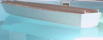
As the deck is not flat the hull is built using three straight "runners" and the ribs are designed to be held in place by the runners until the hull is finished and then the runners are cut off to the deck level. Some ribs are then cut out between the runners to fit in motors and batteries etc.
This construction method is in fact very similar to the way they were actually built! nothing like re-inventing the wheel!
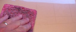
I used Balsa wood runners and a balsa keel but next time I will use something a little less flexible for the runners as they did bend a bit as you can see in the top photo!
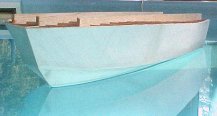
Still a fine looking hull though
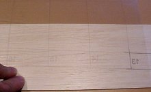
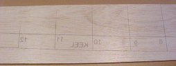
Print the ribs and keel pictures on to a sheet of mylar film or onto the wrong side or wrong type of overhead projection film with an A3 bubble jet printer so that the ink doesn't ever dry (I use a Canon BJC 4550), turn the film over and lay it carefully on the timber and rub the (inverted) wet ink image down onto the wood with a damp sponge, then cut out lots of ribs. I have considered that maybe there are too many ribs!
The Canon ink is water based so it's fairly easy to clean off the kitchen bench but keep some bleach type cleaner nereby just in case the lady of the house comes home, they just don't understand!
You may need to scale these pictures up or down with some sort of graphics package to get them right, I used Paint Shop Pro as a test and it allows scaling in 1% increments.
Check print at least one rib (ribs.gif) on to paper to get it right first.
All images were scaled the same way and at the same time out of Autocad as *.wmf and into Paint Shop Pro and then out again as *.gif but I haven't printed all of them out this way so I take no responsibility for any variations in scale!
Some feedback would be good! jdrain@ridge.com.au
THE COVERING
The hull pictures above show the boat covered with tissue and dope but as yet unpainted, it's very waterproof.
I covered the hull in strips of 1.6mm thick balsa about 30mm wide and laid them on an angle of about 45 degrees to the centreline of the boat and butted them up against each other with
good quality medium thickness superglue (some prefer PVA but it's too slow for me), this strip approach helps to make the compound curves as each strip is mostly just curved in one
direction and is in fact very similar to the original construction with 3"
or 4" mahogany planking. Sand the surface lightly with a sheet of fine
sandpaper glued onto a long piece of wood (like a file) and then start another layer of balsa at 45 degrees in the opposite direction so you make a 2 ply and then after sanding lightly cover that with the tissue and dope.
When buying your balsa for the covering try to select all of the balsa to be of
similar hardness or you may over sand some soft strips next to hard strips. You
could also use harder wood, even mahogany for authenticity, which is available
in thin strip form from larger hobby shops. The original Elco boats had a layer
of planking laid at 45 degrees then a layer of waterproofed muslin cloth and
then another layer of planking laid at the opposite 45 degree angle fixed in
place with hundreds of thousands of brass screws (although I have seen some
photo's particularly of restored boats showing the planking running longway's,
maybe these had one layer at 45 degrees and one longways?)
CAUTION: When playing with Dope you MUST do it outside or in an extremely well
ventilated area or you will get as high as a kite!
Start with the stern of the boat, what you do is paint over the finished balsa with the dope, and then quickly lay on the tissue and press it down into the dope with a cloth before the dope dries, the dope will soak through the tissue and bond it to the
surface (you can also do it by laying on the tissue and then painting over it
with the dope which soaks through). The dope dries and hardens to a thin and
even surface. Overlap the tissue about 3mm around the corners to the sides and bottom. Do the entire hull in about eight sections plus the stern so each surface has about 2 pieces each, otherwise its too hard to stop it creasing in the compound curves. where it overlaps keep it neat or it will show, so do one half of the bottom and overlap about 3mm over the keel, stern and chine edges, then do the other half of the bottom and overlap the keel again, then do the sides the same way. if you do the rear half of the boat first the vertical overlaps in the middle will be towards the rear and won't be tempted to lift with water rushing past when its all finished. I then lightly sanded the whole surface and did another layer with the joins in
slightly different places.
So with the overlaps over the keel, the chine corner and around the stern I have four layers of tissue which makes it very tough. I didn't get any creases and got an excellent result. You can see the tissue overlaps if you look really close. You could line
the joins up with the camoflauge pattern if you were worried about them.
Then I glued on the chine strips and finished off the top ready for the deck and edge runners around the deck.
Of course many people prefer fibreglass which could be done in a very similar technique but I am very happy with the tissue and I don't tolerate the chemicals that are used for
fibreglass, (MEK yuk!).
Ribs.gif (a compilation showing the relative position of all ribs)
Rib1.gif
Rib1a.gif (this was added to make the front easier to make as I had trouble breaking the chines)
Rib2.gif
Rib3.gif
Rib4.gif
Rib5.gif
Rib6.gif
Rib7.gif
Rib8.gif (This is the widest rib)

Rib9.gif
Rib10.gif
Rib10drive.gif (showing the position of the motors and propellers)
Rib11.gif

Rib12.gif
Rib13.gif (the unlucky one)
Don't forget the holes for the prop shafts, I would suggest making the prop shafts first or at least getting the outer tube so you know what size it is, to get the hole size right, even though I drilled the right size holes I ended up cutting some teeth in the end of an extra piece of prop shaft tube with a file and using it as a long "drill" to get rid of some glue in the holes and to cut through the hull skin from the inside. Because the construction stringers bent slightly, so did the path of the prop shaft holes!
Rib14.gif
Rib15.gif
Rib16.gif
Rib17.gif (This is where the prop shafts enter the boat)
Rib18.gif
Rib19.gif
Rib20.gif
Transom.gif
![]()